
A multi-simulator co-simulation method and system

A co-simulation and simulator technology, applied in the field of simulation, can solve the problems of small scale and the difficulty of a single real-time simulator to meet the real-time and scale requirements of simulation

Active Publication Date: 2022-07-08
清鸾科技(成都)有限公司
View PDF12 Cites 0 Cited by
  • Summary
  • Abstract
  • Description
  • Claims
  • Application Information

AI Technical Summary

Problems solved by technology

[0004] However, the real-time computing performance and simulatable scale of the real-time simulator depend on the computing power of the target machine. The smaller the simulation step size, the greater the calculation pressure, and the smaller the real-time simulation scale
With the increasing demand for power system simulation scale, it is increasingly difficult for a single real-time simulator to meet the real-time and scale requirements of simulation.

Method used


Image

  • A multi-simulator co-simulation method and system
  • A multi-simulator co-simulation method and system
  • A multi-simulator co-simulation method and system

Examples


Embodiment Construction

[0029] In order to make the purposes, technical solutions and advantages of the embodiments of the present application clearer, the technical solutions in the embodiments of the present application will be described clearly and completely below with reference to the drawings in the embodiments of the present application. Obviously, the described embodiments It is a part of the embodiments of the present application, but not all of the embodiments. The components of the embodiments of the present application generally described and illustrated in the drawings herein may be arranged and designed in a variety of different configurations.

[0030] Thus, the following detailed description of the embodiments of the application provided in the accompanying drawings is not intended to limit the scope of the application as claimed, but is merely representative of selected embodiments of the application. Based on the embodiments in the present application, all other embodiments obtained...


PUM


Abstract

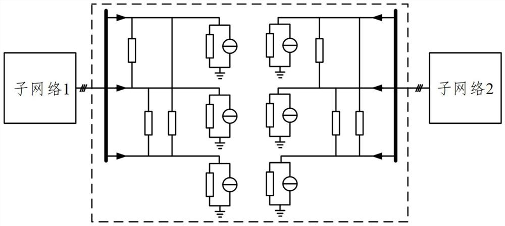
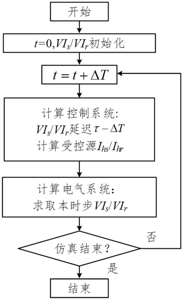
The present application proposes a multi-simulator co-simulation method and system. After the current time step starts, only after the first receiving register of the first emulator obtains the first value, the next action will be performed, and the second value in the first sending register will be transmitted to the second emulator of the second emulator. Receive registers to synchronize the simulation time steps of the two simulators. By defining the first value for the first simulator to perform simulation calculation at the current time step and the second value for the second simulator to perform simulation calculation at the next time step, the delay time for the first simulator to obtain the first value is respectively fixed and the second simulator to obtain the delay time of the second value, so as to ensure that the transmission line decoupling co-simulation algorithm is effective.

Description

technical field [0001] The present application relates to the field of simulation, and in particular, to a multi-simulator co-simulation method and system. Background technique [0002] With the continuous improvement of national electricity demand and the increasing scale of modern power systems, a large number of power electronic equipment such as wind / solar / storage and other renewable energy power generation equipment, HVDC transmission equipment, and microgrid equipment are connected to To the power grid, the operating characteristics and control characteristics of the power grid show strong nonlinear characteristics. In order to realize the accurate analysis of the "power electronic" power system, it is necessary to simulate and reproduce it accurately by means of analog or digital methods. [0003] With the development of computer technology, the digital power system simulation method has been widely used in power system simulation and analysis due to its advantages o...

Claims


Application Information

Patent Timeline
Patent Type & Authority Patents(China)
IPC IPC(8): G06F30/20G06Q50/06
CPCG06F30/20G06Q50/06Y02E60/00
Inventor 宋炎侃于智同
Owner 清鸾科技(成都)有限公司
Learn More