Optical encoder
An optical encoder and encoding technology, applied in optics, optical analog/digital converters, instruments, etc., can solve the problems of difficult optical encoders and high manufacturing costs of high-order ADCs, and achieve the effect of good market competitiveness
- Summary
- Abstract
- Description
- Claims
- Application Information
AI Technical Summary
Problems solved by technology
Method used
Image
Examples
Embodiment 1
[0043] ﹝Embodiment 1﹞
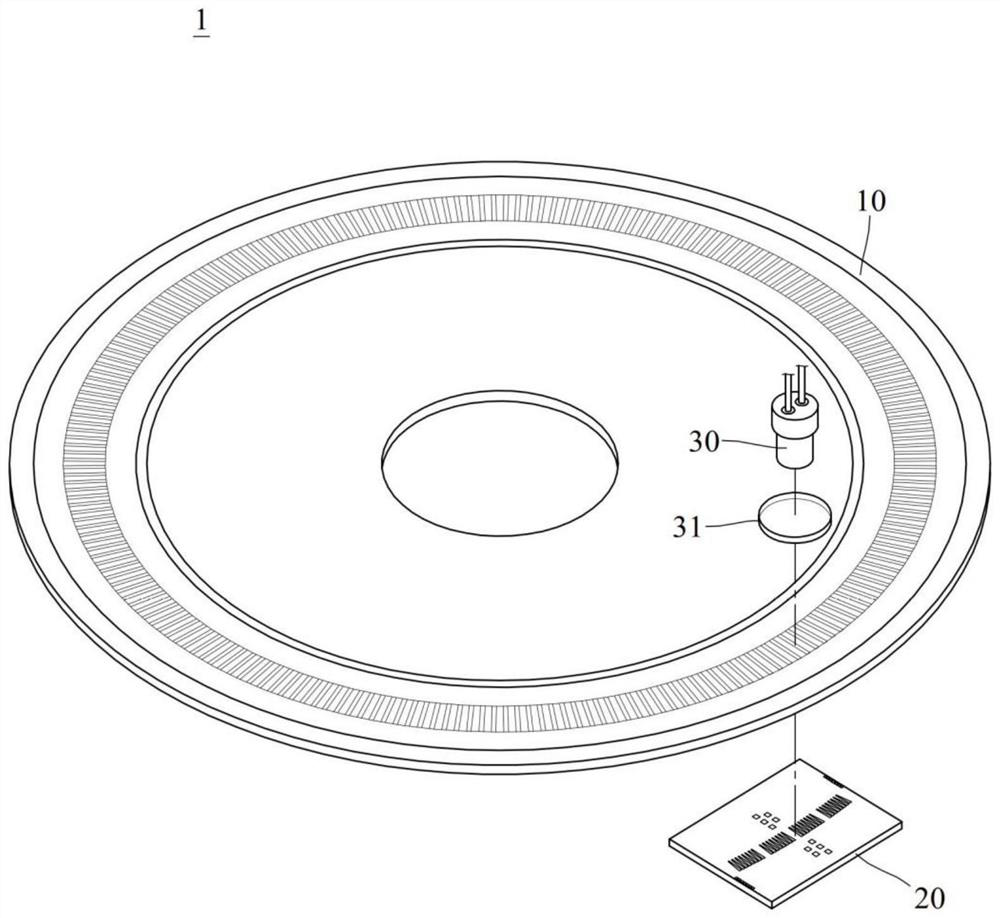
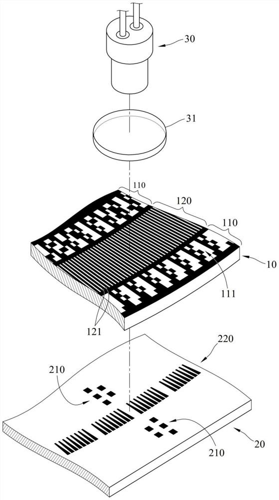
[0044] Embodiment 1 provides such as Figure 1 to Figure 6 The illustrated rotary optical encoder 1 includes a code disc 10 , a light detector 20 , a light source 30 and a sensing circuit 40 . The coding part 120 of the fine division area of the code disc 10 has a plurality of slits 121 which are transparent and spaced apart from each other, and the width of the slits 121 can be 60 micrometers (μm), and the number of the slits 121 is 1024 in total. The specific width and quantity of the slits 121 are only for illustration, and will vary according to the resolution requirement of the subdivided coding portion 120 .
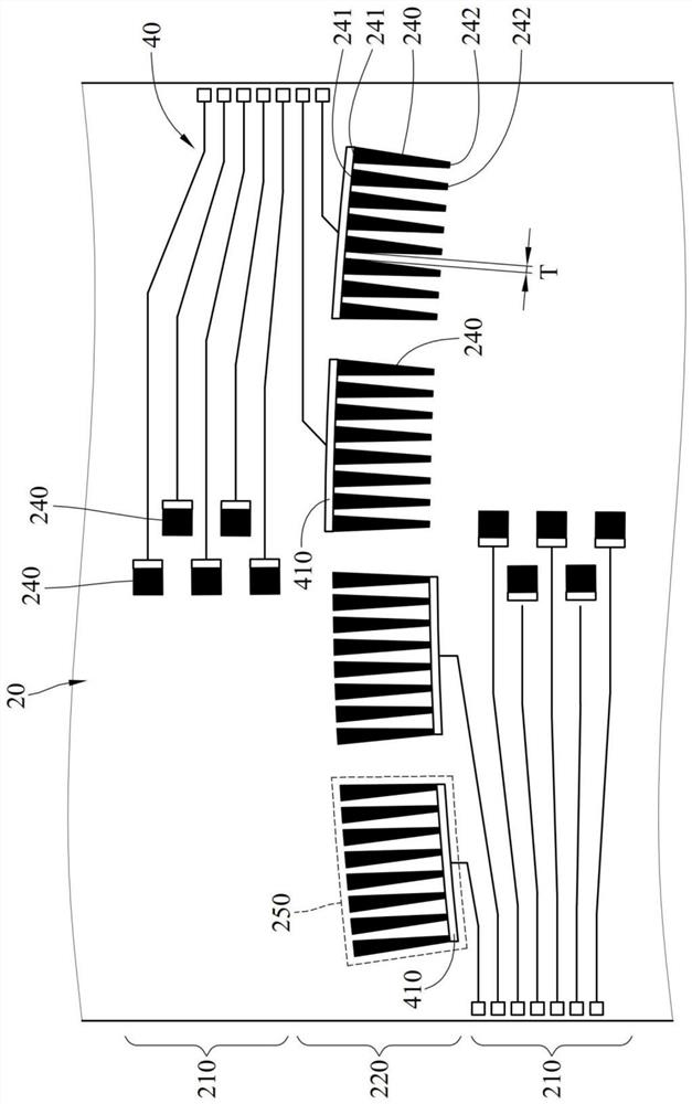
[0045] The photodetector 20 includes a plurality of photosensitive elements 230 located in the photosensitive block 210 of the coding area and the photosensitive block 220 of the subdivision area. The photosensitive elements 230 located in the photosensitive block 220 of the subdivided area are arranged to form a plurality of trapezoidal...
Embodiment 2
[0048] ﹝Embodiment 2﹞
[0049] Embodiment 2 provides a rotary optical encoder 1 , including an encoder disc 10 , a light detector 20 , a light source 30 and a sensing circuit 40 . The coding part 120 of the fine division area of the coding disk 10 has a plurality of slits 121 which are transparent and spaced apart from each other. The number of slits 121 is 1024 in total.
[0050] The photodetector 20 includes a plurality of photosensitive elements 230 located in the photosensitive block 210 of the coding area and the photosensitive block 220 of the subdivision area. The photosensitive elements 230 located in the photosensitive block 220 of the subdivided area are arranged to form a plurality of trapezoidal photosensitive arrays 240 , and eight adjacent photosensitive arrays 240 form a photosensitive array group 250 . Any photosensitive array 240 includes 2960 photosensitive elements 230 arranged in 25 rows. The bottom row of the photosensitive array 240 contains 7 photos...
PUM
 Abstract
Description
Claims
Application Information
 - R&D
- Intellectual Property
- Life Sciences
- Materials
- Tech Scout
- Unparalleled Data Quality
- Higher Quality Content
- 60% Fewer Hallucinations
Browse by: Latest US Patents, China's latest patents, Technical Efficacy Thesaurus, Application Domain, Technology Topic, Popular Technical Reports.
© 2025 PatSnap. All rights reserved.Legal|Privacy policy|Modern Slavery Act Transparency Statement|Sitemap|About US| Contact US: help@patsnap.com


