Electromagnetic induction device used for electric clothes drying machine and operation method of electromagnetic induction device
A technology of electromagnetic induction and operation method, applied in washing devices, other drying devices, applications, etc., can solve problems such as the rise of the clothes dryer, the deformation of the bracket microswitch, and the damage of the microswitch, so as to prolong the service life, The effect of good market competitiveness
- Summary
- Abstract
- Description
- Claims
- Application Information
AI Technical Summary
Problems solved by technology
Method used
Image
Examples
Embodiment 1
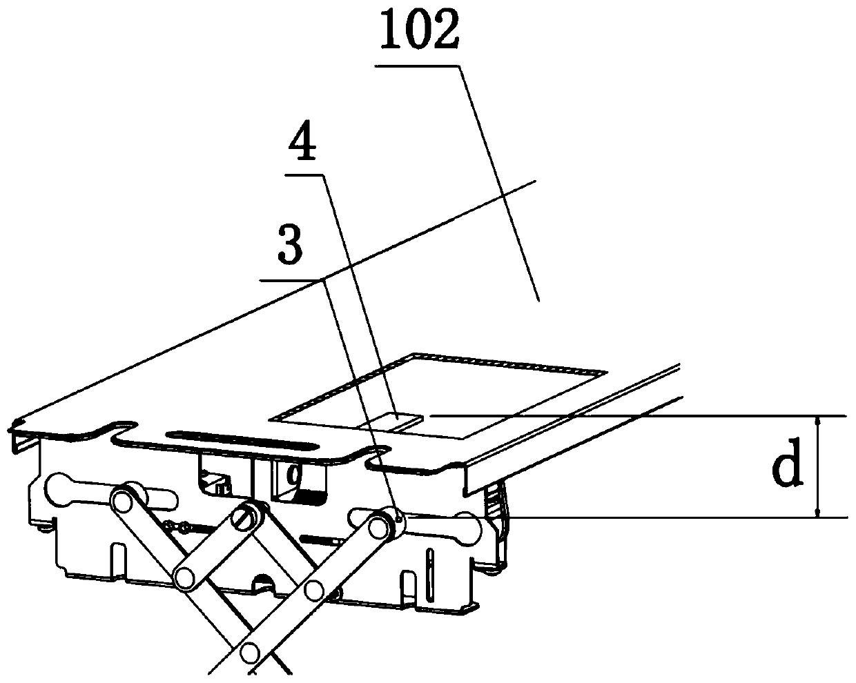
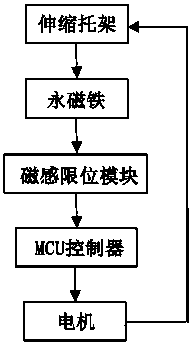
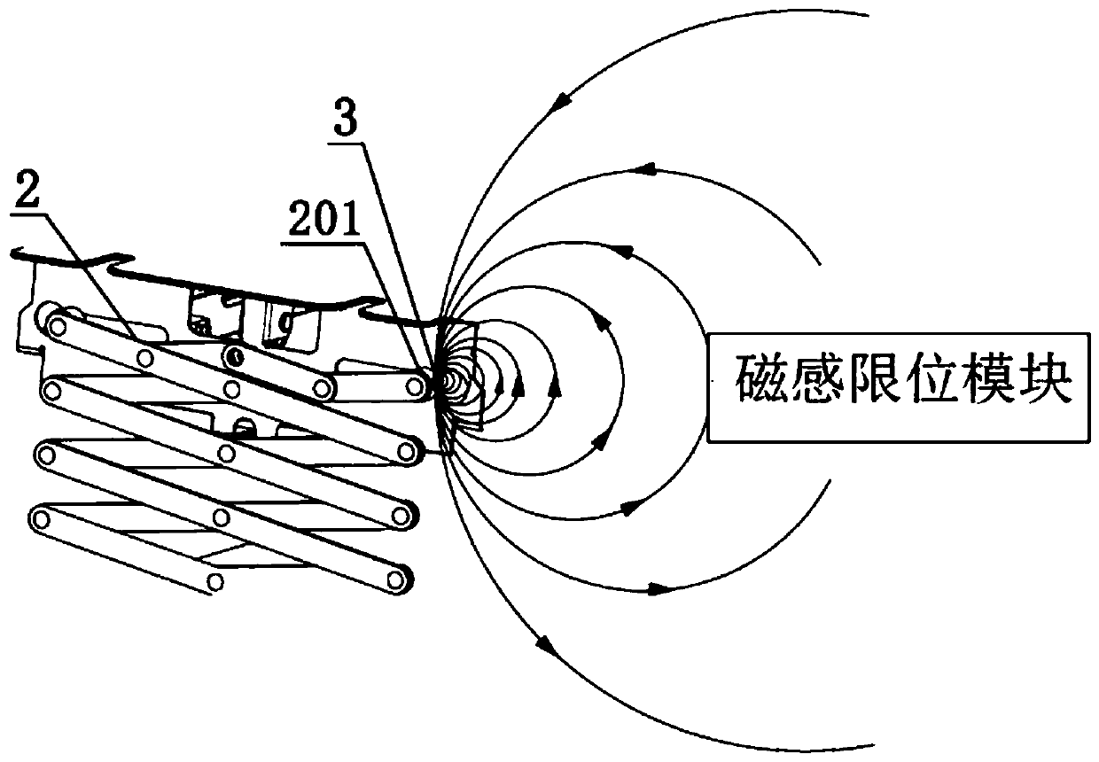
[0042] When the motor controls the telescopic bracket 2 to move from the lower limit position to the upper limit position, the permanent magnet 3 moves towards the direction close to the magnetic induction limit module in the movable slot 101 along with the upper movable end 201 of the telescopic bracket 2 at the same time, as image 3 As shown, when the telescopic bracket 2 moves to the upper limit position, the distance between the permanent magnet 3 on the upper movable end 201 and the magnetic induction limiting module 4 reaches the minimum value, and the magnetic induction limiting module 4 receives the signal from the permanent magnet 3 Maximum magnetic field strength value H max And get the corresponding analog signal, further send out the pulse signal to change the maximum magnetic field strength value H max Send to the MCU controller, and the MCU controller receives the maximum magnetic field strength value H max , and further set the maximum magnetic field strength va...
Embodiment 2
[0044] This embodiment is the same as Embodiment 1, except that the operation sequence is just reversed.
[0045] The motor controls the telescopic bracket 2 to move from the upper limit position to the lower limit position, and at the same time the permanent magnet 3 moves in the movable groove 101 along with the upper movable end 201 of the telescopic bracket 2 in a direction away from the magnetic induction limiting module 4, as Figure 4 As shown, when the telescopic bracket 2 moves to the lower limit position, the distance between the permanent magnet 3 on the upper movable end 201 and the magnetic induction limiting module 4 reaches the maximum value, and the magnetic induction limiting module 4 receives the signal from the permanent magnet 3 Minimum magnetic field strength value H min And get the corresponding analog signal, further send out the pulse signal to set the minimum magnetic field strength value H min Send to the MCU controller, and the MCU controller receiv...
PUM
 Abstract
Description
Claims
Application Information
 - R&D
- Intellectual Property
- Life Sciences
- Materials
- Tech Scout
- Unparalleled Data Quality
- Higher Quality Content
- 60% Fewer Hallucinations
Browse by: Latest US Patents, China's latest patents, Technical Efficacy Thesaurus, Application Domain, Technology Topic, Popular Technical Reports.
© 2025 PatSnap. All rights reserved.Legal|Privacy policy|Modern Slavery Act Transparency Statement|Sitemap|About US| Contact US: help@patsnap.com


