
A remote wireless control system of a cutting and separating device and its application method

A technology of remote wireless and separation devices, which is applied in signal transmission systems, instruments, blasting, etc., and can solve problems such as loopholes, low security of wireless control systems, and potential safety hazards

Active Publication Date: 2022-06-28
苏州信卓胜电子科技有限公司
View PDF15 Cites 0 Cited by
  • Summary
  • Abstract
  • Description
  • Claims
  • Application Information

AI Technical Summary

Problems solved by technology

[0002] Control equipment is a device used to control actuators and collect sensor data in the industrial production process, including the field control unit of the distributed control system, the programmable logic controller and the remote terminal unit to control the production process. The existing For remote wireless cutting and separating devices, the security of the wireless control system is relatively low, and through simple unlocking control, it is relatively easy to have loopholes, especially for remote wireless cutting and separating devices, there are certain security risks

Method used


Image

  • A remote wireless control system of a cutting and separating device and its application method
  • A remote wireless control system of a cutting and separating device and its application method
  • A remote wireless control system of a cutting and separating device and its application method

Examples


Embodiment 1

[0041] Embodiment 1, the state check before use, includes the following steps:

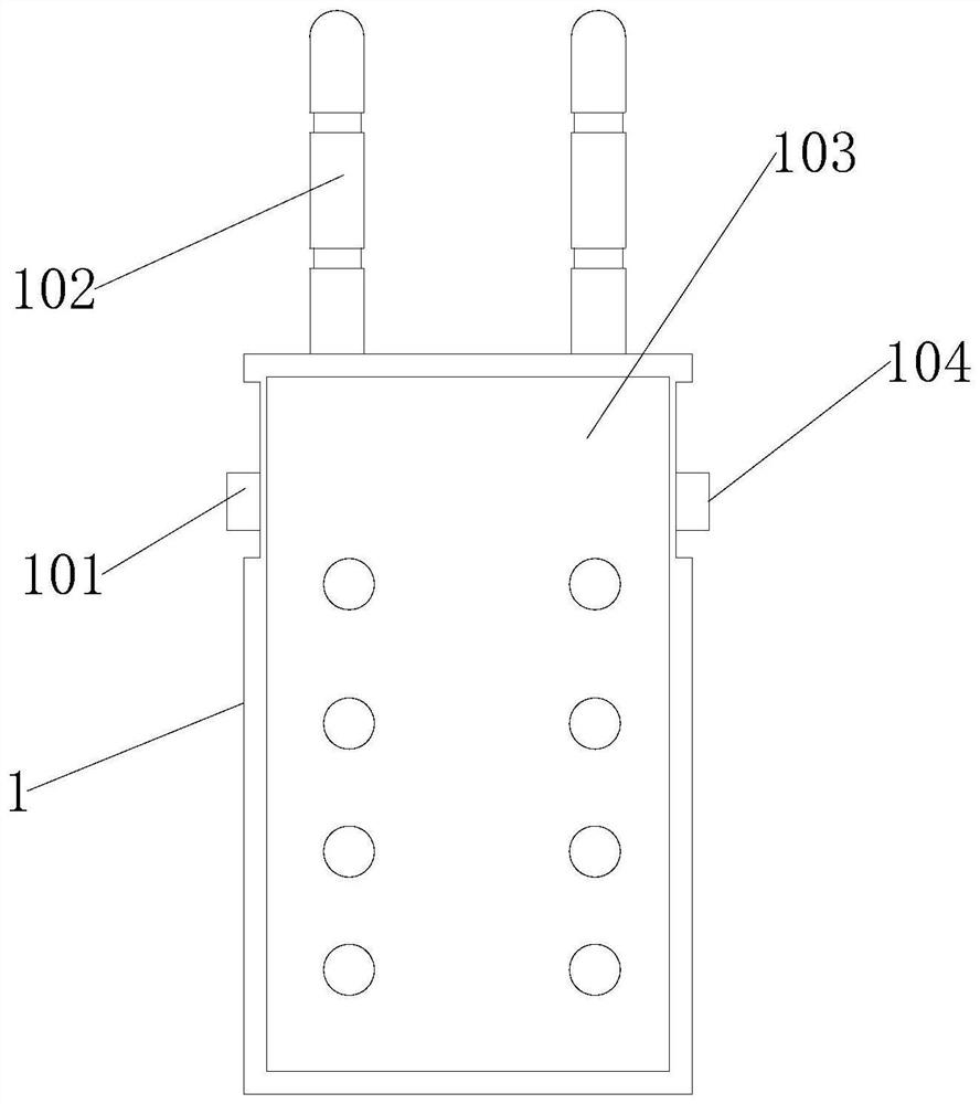
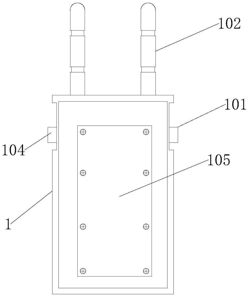
[0042] Step 1, first check whether the antenna installation of signal transmitter 1 or signal receiver 2 is normal, and the antenna should not be loose, fall off, or not installed properly;

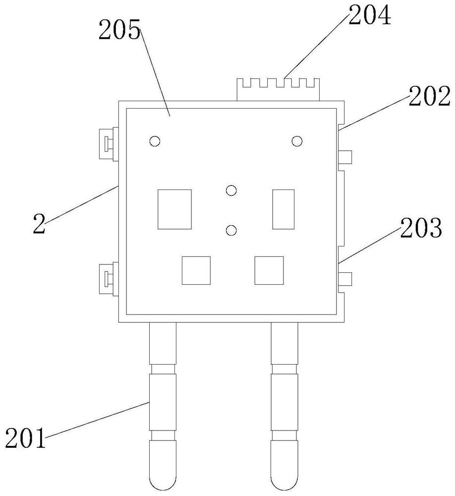
[0043] Step 2: Before turning on the power switch 1 101 of the signal transmitter 1 or the power switch 2 202 of the signal receiver 2, make sure that the enable switch 1 104 or the enable switch 2 203 is in the "off" position, that is, the switch direction is downward. ;

[0044]Step 3, then carry out the pyrotechnic installation. It is strictly prohibited to perform the pyrotechnic installation operation when the power switch 202 or the enabling switch 203 of the signal receiver 2 is turned on. The pyrotechnic terminal 204 of the signal receiver 2 is divided into: For two groups, connect one pyrotechnic product each, peel off the lead end of the pyrotechnic product to expose 4-6mm of the wire core, press t...

Embodiment 2

[0045] Embodiment 2, using process operation, comprises the following steps:

[0046] Step one, power up

[0047] Turn on the power switch 1 101 of the signal transmitter 1 or the power switch 2 202 of the signal receiver 2, that is, the power switch 1 101 and the power switch 2 202 are pulled up, the system is powered on, the power indicator light is on, and after the self-test is passed, the power indicator light and one channel indicator is on, if enable switch one 104 or enable switch two 203 self-check fault, the power indicator, two channel indicators, and communication indicator are on, and the digital tube displays the number 8, please enable switch one 104 or enable switch two 203 is toggled downward. After toggle, the self-check fault state of enable switch one 104 or enable switch two 203 should disappear. If it does not disappear, please stop using the product. If the fault is detected, the power indicator and the communication indicator are on, and the power need...

Embodiment 3

[0058] Embodiment 3, battery replacement, including the following steps;

[0059] a First turn off the power switch one 101 and enable switch one 104 of the signal transmitter 1 or turn off the power switch two 202 and enable switch two 203 of the signal receiver 2;

[0060] b Then use a Phillips screwdriver to remove the cover of the battery compartment, and take out the old battery. Both the signal transmitter 1 and the signal receiver 2 are powered by two military AA batteries in parallel to ensure that the working time is longer than 24 hours. Use a multimeter to measure the battery voltage of the new battery, and the qualified voltage range is between 3.56V and 3.66V. After the test is qualified, install the new battery, and screw in the screw to fix the battery compartment cover, and the battery replacement is completed;

[0061] c After each battery replacement operation, it is necessary to clear the power record, turn on the power switch 1 101 or the power switch 2 202...


PUM


Abstract

The invention discloses a remote wireless control system of a cutting and separating device and a method for using the same. The invention relates to the technical field of remote wireless control of a wireless cutting and separating device. The remote wireless control system of a cutting and separating device includes a signal receiver and a signal transmitter. The input terminal of the signal receiver is connected to the output terminal of the signal transmitter; the signal transmitter is composed of a power switch 1, a control panel 1, an antenna 1, an enabling switch 1 and a battery compartment 1; the control panel 1 includes communication detection, charging, detonation, Check mark, power 0~A and channel function; the signal receiver is composed of power switch 2, control panel 2, antenna 2, enabling switch 2, battery compartment 2 and wiring terminals; control panel 2 includes check mark, power 0~A And the channel function; the beneficial effect of the present invention is: by adding double switches for protection, the safety performance of the remote wireless control system is improved, and loopholes are avoided.

Description

technical field [0001] The invention relates to the technical field of remote wireless control of wireless cutting and separating devices, in particular to a remote wireless control system for cutting and separating devices and a method of using the same. Background technique [0002] Control equipment is a device used to control actuators and collect sensor data in the industrial production process, including the field control unit, programmable logic controller and remote terminal unit of the distributed control system to control the production process. Unit equipment, the existing The wireless control system of the remote wireless cutting and separating device has relatively low security, and through simple unlocking control, loopholes are prone to occur, especially for the remote wireless cutting and separating device, there are certain security risks. SUMMARY OF THE INVENTION [0003] The purpose of the present invention is to solve the above-mentioned problems and de...

Claims


Application Information

Patent Timeline
Patent Type & Authority Patents(China)
IPC IPC(8): F42D1/045G08C17/02
CPCF42D1/045G08C17/02
Inventor 金根王玉伟徐建裴文祥赵路旭汪先超
Owner 苏州信卓胜电子科技有限公司
Learn More