
Textile yarn batch dip dyeing fixing frame

A textile yarn batching technology, which is applied in the field of textile yarn batch dyeing fixtures, can solve the problems of uneven and insufficient dyeing of yarns, the inability to batch dye many yarns, and affect the quality of yarns, etc., to achieve Improve the efficiency and quality of the dye solution, improve the coloring efficiency, and increase the flow speed

Inactive Publication Date: 2021-07-16
苟旭
View PDF0 Cites 1 Cited by
  • Summary
  • Abstract
  • Description
  • Claims
  • Application Information

AI Technical Summary

Problems solved by technology

[0005] The invention can solve the problem that the existing textile yarn dip-dyeing fixing frame cannot separate multiple yarn bobbins in layers, which leads to the problem that multi-strand yarns are easily entangled and knotted during yarn dip-dyeing, which affects the dyeing efficiency of yarn dip-dyeing. , it can also solve the problem that the existing textile yarn dip dyeing fixture cannot be used for batch dyeing of multiple yarns, the dip dyeing efficiency is low, and the yarn cannot be completely contacted with the dye solution, resulting in uneven and insufficient dyeing of the yarn, which affects the quality of the yarn. After dip dyeing, multiple yarns cannot be wound at the same time, and the winding efficiency is low

Method used


Image

  • Textile yarn batch dip dyeing fixing frame
  • Textile yarn batch dip dyeing fixing frame
  • Textile yarn batch dip dyeing fixing frame

Examples


Embodiment Construction

[0028] The embodiments of the present invention will be described in detail below with reference to the accompanying drawings, but the present invention can be implemented in many different ways defined and covered by the claims.

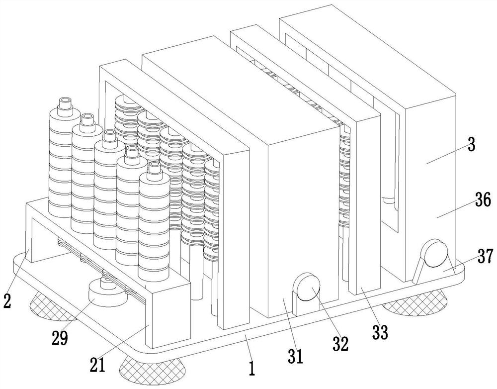
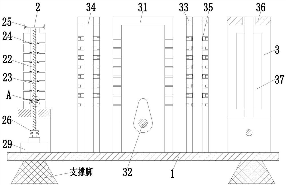
[0029] Such as Figure 1 to Figure 7 As shown, a batch dyeing fixing frame for textile yarns includes a bottom plate 1, a yarn bobbin fixing mechanism 2 and a dip dyeing winding mechanism 3. The bottom plate 1 is provided with a yarn bobbin fixing mechanism 2 on the left side of the upper end surface, and the yarn bobbins are fixed The right side of the mechanism 2 is provided with a dip dyeing winding mechanism 3 , and the dip dyeing winding mechanism 3 is installed on the base plate 1 .

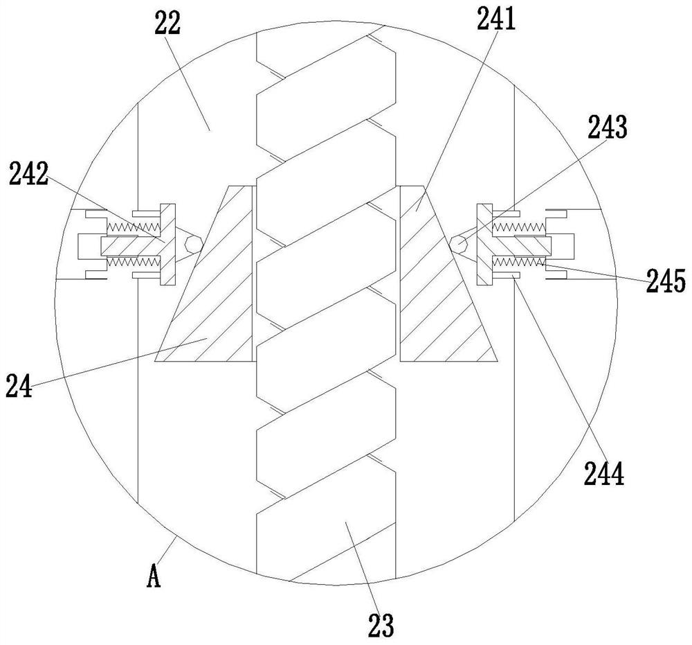
[0030]The bobbin fixing mechanism 2 includes an unwinding frame 21, a support rod 22, a threaded rod 23, a layered limit branch chain 24, a lock nut 25, a transmission wheel 26, a belt 27, a driving motor 28 and a disc plate 29 , the left side of the upper end s...


PUM


Abstract

The invention relates to a textile yarn batch dip-dyeing fixing frame. The fixing frame comprises a bottom plate, a spool fixing mechanism and a dip-dyeing winding mechanism, the spool fixing mechanism is arranged on the left side of the upper end face of the bottom plate, the dip-dyeing winding mechanism is arranged on the right side of the spool fixing mechanism, and the dip-dyeing winding mechanism is installed on the bottom plate. The textile yarn batch dip-dyeing fixing frame can solve the problems that an existing textile yarn-dip dyeing fixing frame cannot separate a plurality of bobbins for winding yarns in a layered mode, so that multiple strands of yarns are prone to winding and knotting in the yarn dip-dyeing process, and the yarn dip-dyeing coloring efficiency is affected, and can also solve the problems that an existing textile yarn dip-dyeing fixing frame cannot conduct batch dip-dyeing on multiple pieces of yarns, the dip-dyeing efficiency is low, the yarn cannot make thorough contact with dye liquor, consequently, yarn dyeing is uneven and insufficient, yarn quality is affected, multiple strands of yarn cannot be wound at the same time after dip-dyeing, and the winding efficiency is low.

Description

technical field [0001] The invention relates to the technical field of textile yarn dip-dyeing, in particular to a fixing frame for batch-based dip-dyeing of textile yarns. Background technique [0002] Yarn is a kind of textile, which is processed into products of a certain fineness with various textile fibers. It is used for weaving, rope making, thread making, knitting and embroidery, etc. It is divided into staple fiber yarn, continuous filament, etc. There are many varieties and different properties. It can be pure spinning made of natural fibers or various chemical short fibers, or a blended yarn made of several fibers, or it can be directly sprayed from chemical fibers. Processed filament yarn. Exhaust dyeing, also known as exhaust dyeing, is a term used for dyeing. The method of immersing the dyed object in a dye bath containing dyes and required auxiliaries, and gradually dyeing the dyed object with the dye through the circulation of the dye bath or the movement o...

Claims


Application Information

Patent Timeline
Patent Type & Authority Applications(China)
IPC IPC(8): D06B3/04D06B23/04D06B23/20B65H57/14B65H54/20B65H54/54B65H54/70B65H54/72B65H54/74
CPCB65H54/20B65H54/54B65H54/70B65H54/72B65H54/74B65H57/14B65H2701/174B65H2701/31D06B3/04D06B23/04D06B23/20
Inventor 苟旭
Owner 苟旭
Learn More