
Guidable valve suturing device and valve suturing system

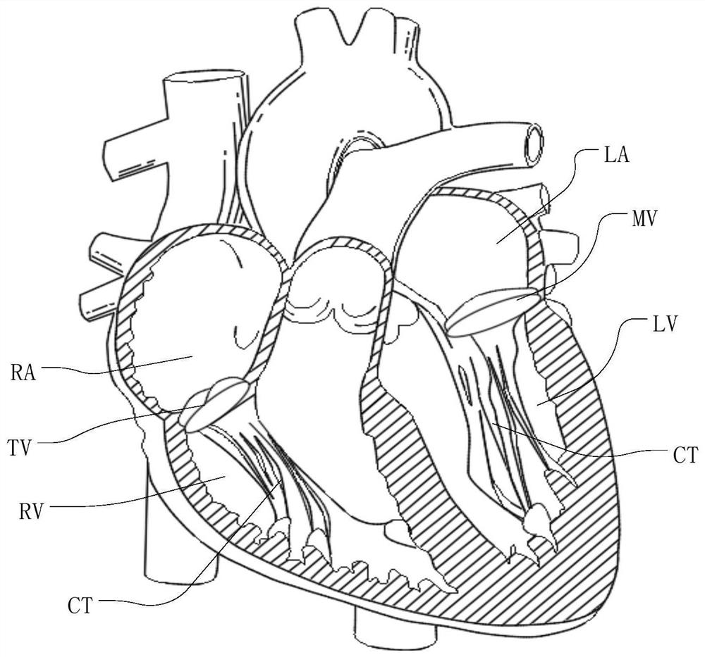
A suture device and valve technology, applied in the field of medical devices, can solve the problems such as the inability of the puncture needle to connect the suture, the flow back, the rotation of the collet push rod, etc.

Pending Publication Date: 2021-07-16
HANGZHOU VALGEN MEDTECH CO LTD
View PDF0 Cites 0 Cited by
  • Summary
  • Abstract
  • Description
  • Claims
  • Application Information

AI Technical Summary

Problems solved by technology

Mitral regurgitation or tricuspid regurgitation can cause systolic ventricular blood to flow back into the atrium, causing the atria to expand in volume and pressure, leading to increased ventricular load and predisposing to heart failure
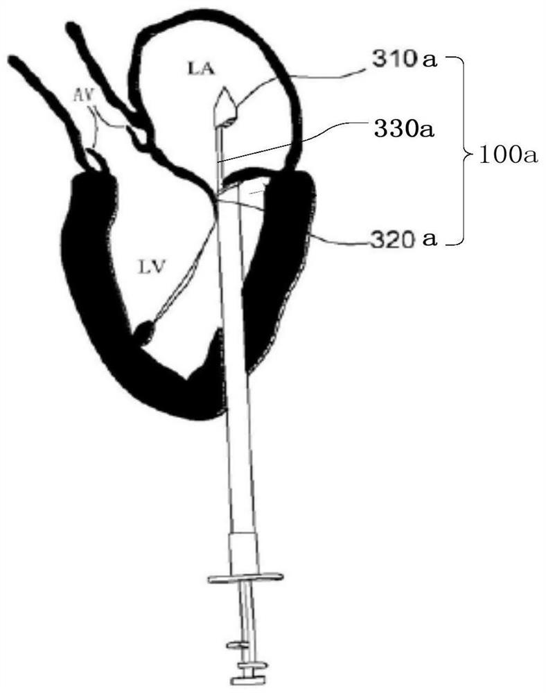
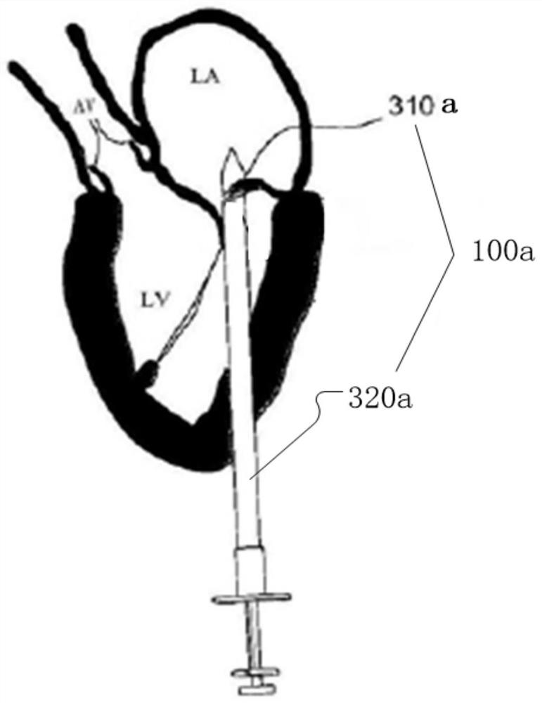
[0006] On the one hand, in actual use, the operator may cause the chuck push rod to rotate due to improper operation or uncontrollable factors, so that the distal chuck 310a and the proximal chuck 320a are misaligned and cannot be aligned, which affects the clamping effect on the valve.
On the other hand, the above-mentioned interventional heart valve repair instrument 100a needs to penetrate the apex of the heart through the transthoracic approach, so it will still cause certain damage to the human body. When the instrument passes through the curved blood vessel, the chuck push rod also needs to have a certain degree of flexibility to bend with the sheath, the chuck push rod is easy to rotate, and the distal chuck and the distal chuck driven by the chuck push rod The relative movement between the proximal chucks may no longer be a linear motion, so the relative positions of the distal chuck and the proximal chuck are prone to shift, so that the suture in the distal chuck may collide with the puncture needle. Misalignment, so that the needle cannot connect to the suture, and the suture cannot be inserted into the valve smoothly

Method used


Image

  • Guidable valve suturing device and valve suturing system
  • Guidable valve suturing device and valve suturing system
  • Guidable valve suturing device and valve suturing system

Examples


no. 2 approach

[0097] see Figure 22 , Figure 22 It is a partial structural schematic diagram of the valve suture system provided in the second embodiment of the present application.

[0098] The structure of the valve suture system provided by the second embodiment of the present application is substantially similar to that provided by the first embodiment, except that the guide rod 523 is fixedly connected between the stopper 524 and the spacer 529; The rod 526 is fixed on the limiting member 524 and extends away from the pad 529 . The chuck push rod 526 is a solid rod to increase the strength of the chuck push rod 526 .

[0099] In this embodiment, the shape of the guide rod 523 is a cylinder and the number is two. The guide rods 523 are arranged at intervals. It can be understood that the shape of the guide rod 523 is not limited to be a cylinder and the number is two. For example, the shape of the guide rod 523 can be but not limited to be a cylinder and the number can be three, or...

no. 3 approach

[0104] Please refer to Figure 23 and Figure 24 , Figure 23 It is a partial structural schematic diagram of the valve suture system provided in the third embodiment of the present application. Figure 24 It is a cross-sectional view of the chuck push rod and the stopper of the valve suture system provided in the third embodiment of the present application.


PUM


Abstract

The invention provides a guidable valve suturing device. The guidable valve suturing device comprises a clamping device and a puncture needle, the clamping device comprises a far-end chuck, a near-end chuck, a chuck push rod and a guide rod, the chuck push rod and the guide rod are fixedly connected and movably penetrate through the near-end chuck, at least one of the chuck push rod and the guide rod is fixedly connected with the far-end chuck, the far-end chuck is used for containing a suture, and the puncture needle movably penetrates through the near-end chuck and is used for puncturing a valve and being connected with the suture. The guide rod is arranged, the chuck push rod can be prevented from rotating, and it is guaranteed that the chuck push rod performs linear motion in the process of driving the far-end chuck and the near-end chuck to be opened and closed relatively, so that the relative positions of the far-end chuck and the near-end chuck do not deviate, the peripheral edges can be aligned all the time, the valve is effectively clamped, and the suture in the far-end chuck and the puncture needle are not misplaced and can be smoothly connected, so that the suture is implanted into the valve. The invention further provides a valve suturing system comprising the guidable valve suturing device.

Description

technical field [0001] The invention relates to the technical field of medical devices, in particular to a guideable valve suture device and a valve suture system. Background technique [0002] Heart valve disease is caused by the heart valves (including valves, chordae (such as figure 1 The structural damage, fibrosis, adhesion, shortening, myxomatous degeneration, degenerative changes or congenital malformation, trauma, etc. caused by single valve or multiple valve function or structure abnormalities , leading to valve stenosis and insufficiency. [0003] see figure 1 , left atrium (eg figure 1 LA shown) and the left ventricle (as shown figure 1 LV shown) between the mitral valve (eg figure 1 MV shown) separates the right atrium (eg figure 1 RA shown) and right ventricle (as shown figure 1 RV shown) is formed by the tricuspid valve (eg figure 1 Shown TV) separated, tricuspid valve and mitral valve so that blood can only flow from the atrium into the ventricle, but ...

Claims


Application Information

Patent Timeline
Patent Type & Authority Applications(China)
IPC IPC(8): A61B17/04A61B17/062
CPCA61B17/0469A61B17/0491A61B17/0625A61B17/0482A61B2017/00783A61B17/04A61B17/062
Inventor 李阳张庭超甘义杰
Owner HANGZHOU VALGEN MEDTECH CO LTD
Learn More