
Display driving circuit and driving method of display driving circuit

A display drive and circuit technology, applied to static indicators, instruments, etc., can solve the problems of limited threshold voltage detection range, compensation, and poor data voltage compensation effect, so as to improve display uniformity and reduce current differences , to achieve the effect of compensation

Active Publication Date: 2021-07-13
SHENZHEN CHINA STAR OPTOELECTRONICS SEMICON DISPLAY TECH CO LTD
View PDF5 Cites 1 Cited by
  • Summary
  • Abstract
  • Description
  • Claims
  • Application Information

AI Technical Summary

Problems solved by technology

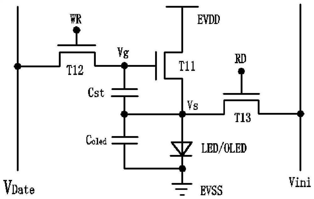
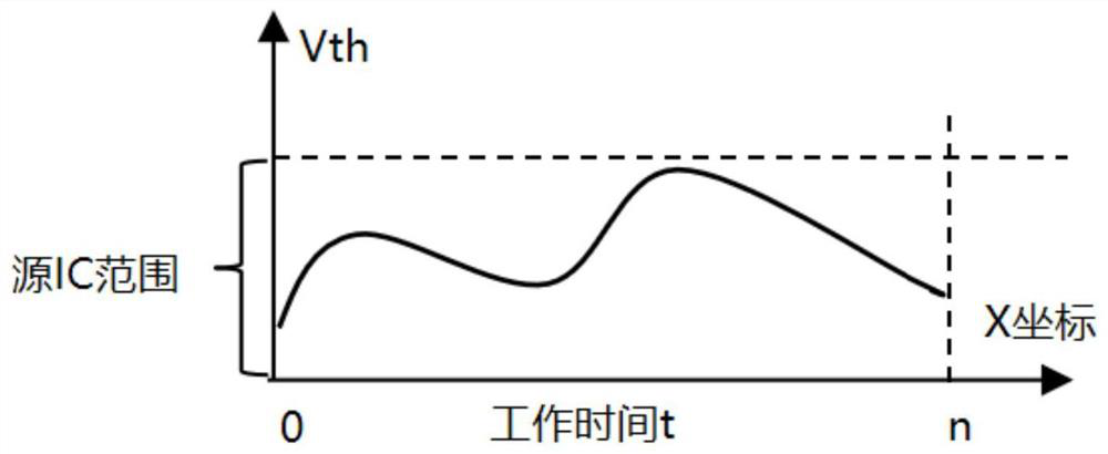
[0006] The present invention provides a display driving circuit and a driving method of the display driving circuit, which can solve the problem that the existing external compensation scheme cannot delay the aging of the driving transistor, and the detection range of the threshold voltage of the ADC module is limited. When the voltage is greater than the driving voltage, the existing threshold voltage detection method cannot accurately detect the threshold voltage change of the pixel circuit, which means that the source driver module cannot perform effective data voltage compensation, resulting in poor compensation effect of the data voltage. , the problem that affects the display uniformity of the display device

Method used


Image

  • Display driving circuit and driving method of display driving circuit
  • Display driving circuit and driving method of display driving circuit
  • Display driving circuit and driving method of display driving circuit

Examples


Embodiment Construction

[0039] The following descriptions of the various embodiments refer to the accompanying drawings to illustrate specific embodiments in which the invention may be practiced. The directional terms mentioned in the present invention, such as [top], [bottom], [front], [back], [left], [right], [inside], [outside], [side], etc., are only for reference The orientation of the attached schema. Therefore, the directional terms used are used to illustrate and understand the present invention, but not to limit the present invention. In the figure, units with similar structures are indicated by the same reference numerals, and the dotted lines in the figure indicate that they do not exist in the structure, and only illustrate the shape and position of the structure.

[0040] In a conventional pixel circuit, the drive transistor is used to control the current flowing through the light-emitting device, thereby controlling the luminance of the light-emitting device. However, in practice, due ...


PUM


Abstract

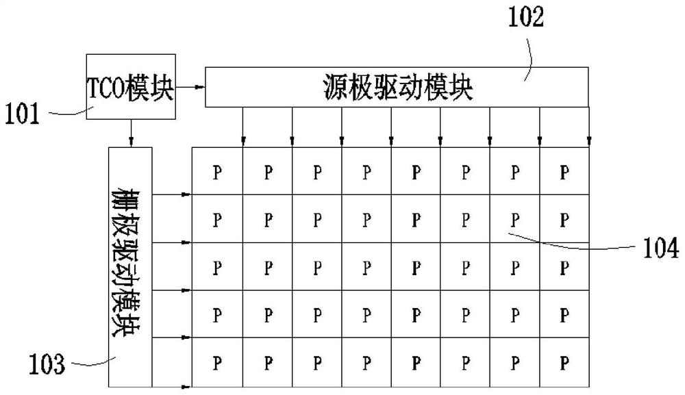
The invention provides a display driving circuit and a driving method of the display driving circuit. A source electrode driving module of the display driving circuit inputs a first data signal to a first input end of a selection module and inputs a control signal to a control end of the selection module, and a reverse bias circuit inputs a second data signal to a second input end of the selection module; in the display time of the display frame period, the selection module outputs the first data signal to the display module, and the display module emits light normally, and in the non-display time of the display frame period, in the non-display frame period or in a shutdown state, the selection module outputs the second data signal to the display module, and a pixel circuit of the display module is in a reverse bias state; the driving transistors are quenched and tempered, the state of electrons is recovered, the aging of the driving transistors is delayed, the threshold voltage Vth characteristic of the driving transistors is compensated, the current difference between the driving transistors is reduced, and the display uniformity of the display module is improved.

Description

technical field [0001] The invention relates to the field of display technology, in particular to a display driving circuit and a driving method for the display driving circuit. Background technique [0002] The existing AMOLED (Active Matrix Organic Light Emitting Diode, Active Matrix Organic Light Emitting Diode) display panel is widely used because it is lighter and thinner than the liquid crystal display panel. Self-luminous displays will cause problems such as life attenuation and afterimage due to the drift of thin-film transistor characteristics. Therefore, the industry is developing a variety of different compensation schemes, which are mainly classified into two types: internal compensation using pixel structure or external compensation with driver chips. Among them External compensation has become a research hotspot for large-size self-luminous displays due to its good compensation effect and high aperture ratio. Most of the existing external compensation schemes ...

Claims


Application Information

Patent Timeline
Patent Type & Authority Applications(China)
IPC IPC(8): G09G3/3225G09G3/3291G09G3/3258
CPCG09G3/3225G09G3/3291G09G3/3258G09G2320/0233Y02D10/00
Inventor 王利民
Owner SHENZHEN CHINA STAR OPTOELECTRONICS SEMICON DISPLAY TECH CO LTD
Learn More