Beam-wall quick-mounting and early-dismounting beam structure facilitating beam bottom adjustment and positioning

A technology for adjusting positioning and beam structure, applied in the treatment of formwork, building construction, and on-site preparation of building components, etc., can solve problems such as affecting concrete quality, uncontrollable and unadjustable supporting force, positioning adjustment, etc., to ensure Beam quality and construction safety, avoid slurry leakage and beam structure deviation, and achieve the effect of installation position

Pending Publication Date: 2021-07-13
广州市快易模板工程有限公司 +1
View PDF0 Cites 1 Cited by
  • Summary
  • Abstract
  • Description
  • Claims
  • Application Information

AI Technical Summary

Problems solved by technology

In this way, when the beam is too large, the supporting strength is not enough, it is difficult to control the straightness of the beam bottom formwork, and it is difficult to correct when there is unevenness
[0003] In addition, because the beam side formwork needs to be reinforced by additional wood squares and steel pipes, the traditional beam wall formwork reinforcement and support methods are cumbersome and unreliable
In addition, wooden squares and round steel pipes are used to reinforce the formwork. Due to its poor rigidity and strength, problems such as formwork deformation are prone to occur, thereby affecting the quality of the entire concrete; at the same time, the bottom of the traditional beam wall formwork and the bottom of the beam are placed closely on the same wooden As a result, it is difficult to realize early demolition and turnover utilization of the beam wall and reinforcement components after the beam pouring is completed
[0004] Moreover, due to the verticality problem of the bottom support of the existing beam wall structure and the error problem of manual installation, there will be gaps or insufficient connection between the beam wall forming formwork and the top panel structure or wall structure. In turn, it will cause grout leakage from the gap when pouring concrete or the expansion mold will cause the forming deviation of the inner corner of the floor
Moreover, the existing beam-wall structure adopts a fixed connection structure on the steel pipe main keel or the wooden sub-keel, and it is extremely difficult to adjust the position of the beam-forming formwork when the beam-wall forming formwork deviates. At the same time, when installing the beam-forming formwork It is also difficult to quickly and effectively adjust the positioning of the beam-wall forming formwork, which will cause position errors after the subsequent beam-wall formwork is fixed
In particular, the standard floors of existing residential buildings use a large number of aluminum molds. The beam top support of the aluminum mold is fixedly connected with the aluminum mold beam, and the position of the beam structure can only be adjusted by moving the beam support pole. Directly adjusting the beam support pole will cause There is a verticality error in the support pole of the aluminum mold jacking, which in turn causes the support force to be uncontrollable and unadjustable, which makes the construction of beams with a high story height a great safety hazard, and it is extremely difficult to implement the construction and positioning adjustment of beams with a story height of more than 4.5 meters

Method used


Image

  • Beam-wall quick-mounting and early-dismounting beam structure facilitating beam bottom adjustment and positioning
  • Beam-wall quick-mounting and early-dismounting beam structure facilitating beam bottom adjustment and positioning
  • Beam-wall quick-mounting and early-dismounting beam structure facilitating beam bottom adjustment and positioning

Examples


Embodiment 1

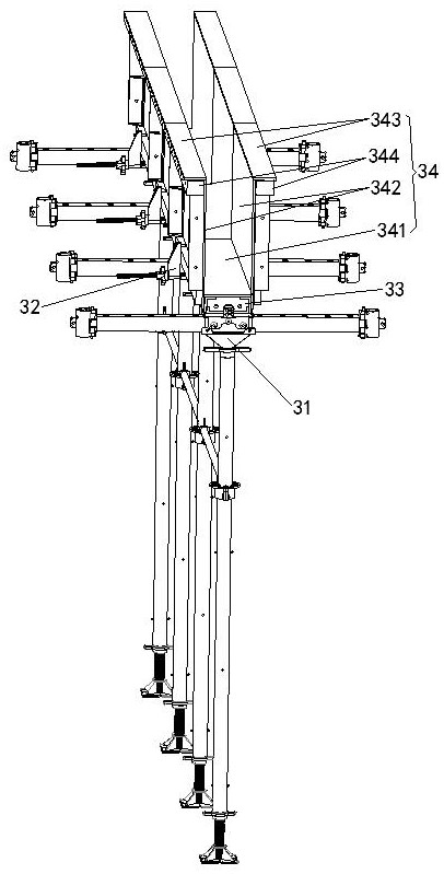
[0058] A beam-wall quick-installation and early-demolition beam structure that facilitates the adjustment and positioning of the beam bottom in this embodiment, such as figure 1 As shown, it includes a beam support assembly 31, a beam bottom keel end fixed connector 33, and a beam structure formwork assembly 34. The top of the beam support assembly 31 is fastened with a beam bottom keel end fixed connector 33, and the beam structure template The assembly 34 includes a beam bottom plate 341, a beam side plate 342 symmetrically arranged on both sides of the beam bottom plate 341, a beam wall inner corner floor formwork 343 arranged on the top of the beam side plate 342, and the bottoms of the beam side plates 342 on both sides extend to the beam bottom plate The lower side of the bottom end surface of 341 and the bottom end surface of the beam bottom plate 341 form a beam bottom groove that is engaged with the fixed connector 33 at the bottom of the beam keel; the tops of the bea...

Embodiment 2

[0062] This embodiment is further optimized on the basis of embodiment 1, such as figure 1 As shown, it also includes the supporting connecting keel 344 of the formwork of the inner corner of the beam wall. And the edge of the beam wall inner corner floor formwork 343 away from the beam side plate 342 extends to the outside of the edge of the beam wall inner corner floor formwork support connecting keel 344 to form a common side structure.

[0063] The formwork support connecting keel 344 of the inner corner of the beam wall is a rectangular beam structure or a U-shaped beam structure. The wall corner floor formwork 343 is supported and reinforced; the left side or the right side of the beam wall corner floor formwork support connection keel 344 corresponds to the left side of the beam side plate 342 on the left side or the beam side plate 342 on the right side The right side is arranged in close contact, and is used to support and reinforce the beam side plate 342, so as to ...

Embodiment 3

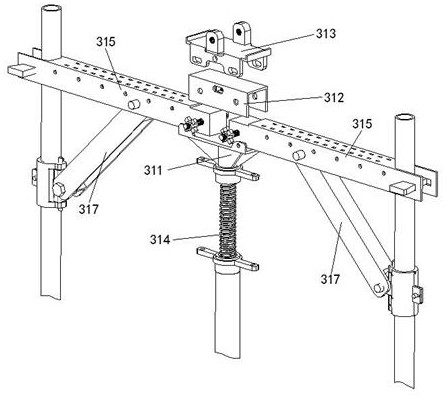
[0067] This embodiment is further optimized on the basis of embodiment 1 or 2, such as figure 2 As shown, the beam support assembly 31 includes a beam support main keel 315, a beam structure lifting support screw assembly 314, a beam structure support tray 311 arranged on the top of the beam structure lift support screw assembly 314, a beam structure support tray 311 arranged on the beam structure support tray 311 The top beam structure supports and connects the jacking bracket 312, and the beam structure positioning adjustment supporting jacking bracket 313 arranged on the top of the beam structure supporting and connecting the jacking bracket 312, the top of the beam structure lifting and supporting screw assembly 314 penetrates the beam structure supporting tray 311 upwards And it is connected with the bottom of the beam structure support connection top bracket 312, the left and right symmetrical engagement between the beam structure support connection top bracket 312 and t...


PUM


Abstract

The invention discloses a beam-wall quick-mounting and early-dismounting beam structure facilitating beam bottom adjustment and positioning. The beam-wall quick-mounting and early-dismounting beam structure facilitating beam bottom adjustment and positioning comprises a beam support assembly, a beam bottom keel end fixed connecting piece and a beam structure formwork assembly, wherein the top of the beam support assembly is provided with the beam bottom keel end fixed connecting piece in a buckling mode, and the beam structure formwork assembly comprises a beam bottom plate, beam side plates symmetrically arranged on the two sides of the beam bottom plate and a beam wall internal corner floor formwork arranged on the tops of the beam side plates; the bottoms of the beam side plates extend to the lower side of the bottom end face of the beam bottom plate, and the bottoms of the beam side plates and the bottom end face of the beam bottom plate form a beam bottom groove clamped with the beam bottom keel end fixed connecting piece; the tops of the beam side plates on the two sides extend to the upper side of the top end face of the beam bottom plate and form a beam pouring groove with the top end face of the beam bottom plate. According to the beam-wall quick-mounting and early-dismounting beam structure facilitating beam bottom adjustment and positioning, the beam structure formwork assembly can be quickly positioned, and meanwhile, the mounting position of the beam structure formwork assembly can be flexibly and quickly adjusted so as to eliminate position errors, so that the beam structure formwork assembly and a top panel assembly or a wall body can be tightly spliced; meanwhile, a split type beam wall supporting structure is adopted, the construction efficiency of a beam wall structure is greatly improved, the beam side plates, beam main keels, beam reinforcing assemblies and the like can be dismounted and recycled at the same time after concrete pouring and tamping are completed for 24 hours, and the material cost is greatly saved.

Description

technical field [0001] The invention belongs to the technical field of beam wall construction in building formwork engineering, and in particular relates to a beam wall quick-installation and early-dismantling beam structure which is convenient for beam bottom adjustment and positioning. Background technique [0002] At present, in building construction, when concrete components such as beams are poured on site, formwork, wooden squares, round steel pipes, and traditional steel pipe supports are often used to assemble them. However, due to technical limitations, wooden squares need to be placed under the wooden formwork for reinforcement and support. Both steel pipes or wooden squares are used as the main flute on the two rows of steel pipe supports, and then wooden squares are placed horizontally on the main flute, and finally on the wooden squares. Place beam base formwork and beam wall formwork. In this way, when the beam is too large, the support strength is not enough,...

Claims


Application Information

Patent Timeline
IPC IPC(8): E04G13/04E04G17/00E04G19/00
CPCE04G13/04E04G17/001E04G19/00
Inventor 付志红
Owner 广州市快易模板工程有限公司
Why Eureka
Try Eureka