Drawer type washing machine
A washing machine and drawer-type technology, applied in the control device of washing machine, washing device, textile and paper making, etc., can solve the problems of unsatisfactory degree of automation, manual control and manual opening by users, etc.
- Summary
- Abstract
- Description
- Claims
- Application Information
AI Technical Summary
Problems solved by technology
Method used
Image
Examples
Embodiment 1
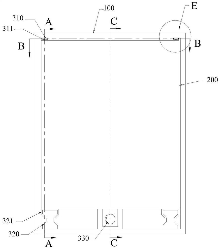
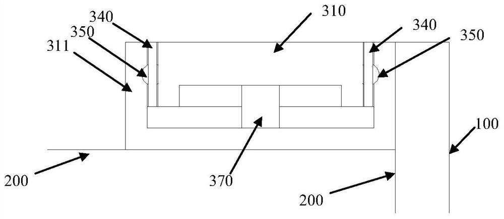
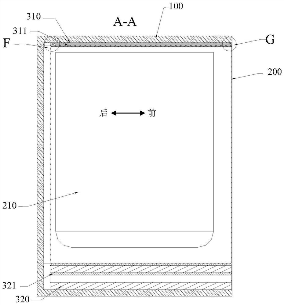
[0079] Such as Figure 1 to Figure 8 As shown, the pull-out limiter includes an upper slide rail pull-out limit structure 361 arranged on the upper slide rail 311, and an upper rail pull-out limit structure 360 arranged on the upper rail 310. The first position detection device 400 includes a first detection terminal and a first detected terminal, and the first detection terminal is arranged on the pull-out limit structure 360 of the upper rail (such as Figure 5 shown), the first detected terminal is set on the pull-out limit structure 361 of the upper slide rail (such as Figure 4 shown). In another embodiment, the first detection terminal is set on the pull-out limit structure 361 of the upper slide rail (such as Figure 4 shown), the first detected terminal is set on the pull-out limit structure 360 of the upper rail (such as Figure 5 shown).
[0080]Preferably, the first detection terminal is fixed, set on the pull-out limit structure 360 of the upper rail, a...
Embodiment 2
[0095] This embodiment introduces another setting method of the in-position detection device. The main difference between this embodiment and Embodiment 1 is that the position of the pull-out limit part is different, and the first limit column and the first limit groove are no longer added. , directly use the existing structure to limit the pull-out of the drawer 200, and the setting of the pushing limit part is the same as that in the first embodiment.
[0096] Such as Figure 1 to Figure 9 As shown, the upper slide rail 311 is a chute with an upward opening, and has two opposite vertical side walls and a bottom wall fixedly connected with the drawer 200; Vertical side walls and a top wall fixedly connected with the machine body 100 . The inner wall surface of the two vertical side walls of the upper slide rail 311 is provided with a first chute 314, the outer wall surface of the two vertical side walls of the upper rail 310 is provided with a second chute 315, the first chu...
Embodiment 3
[0104] This embodiment introduces another setting method of the in-position detection device. The main difference between this embodiment and Embodiment 1 is that the limit post no longer uses the first limit post and the second limit post. The limit posts in place have the same structure, and are arranged on the upper rail 310 or the upper slide rail 311 .
[0105] In this embodiment, a situation in which the limiting column is arranged on the upper slide rail 311 is used for illustration.
[0106] combine figure 1 , image 3 , Figure 5 , Figure 6 , Figure 8 , Figure 9 , Figure 11 to Figure 14 The upper sliding rail pull-out limiting structure 361 is a limiting column arranged at the end of the upper sliding rail 311 away from the opening of the body 100 (such as Figure 12 shown), the upper rail pull-out limiting structure 360 is a first limiting groove arranged at one end of the upper rail 310 close to the opening of the body 100 (such as Figure 5 As shown),...
PUM
 Abstract
Description
Claims
Application Information
 - Generate Ideas
- Intellectual Property
- Life Sciences
- Materials
- Tech Scout
- Unparalleled Data Quality
- Higher Quality Content
- 60% Fewer Hallucinations
Browse by: Latest US Patents, China's latest patents, Technical Efficacy Thesaurus, Application Domain, Technology Topic, Popular Technical Reports.
© 2025 PatSnap. All rights reserved.Legal|Privacy policy|Modern Slavery Act Transparency Statement|Sitemap|About US| Contact US: help@patsnap.com


