
Wheel-foot type robot suspension mechanism, axle module and chassis

A suspension mechanism and robot technology, which can be used in motor vehicles, transportation and packaging, etc., can solve the problems of insufficient natural structural rigidity and inability to drive at high speed, and achieve the effect of strong off-road performance and maneuverability.

Pending Publication Date: 2021-07-13
陈晓妮
View PDF7 Cites 0 Cited by
  • Summary
  • Abstract
  • Description
  • Claims
  • Application Information

AI Technical Summary

Problems solved by technology

[0003] However, the structure of most wheel-footed robots is only a simple combination. This simple combination does not change the leg structure of the legged robot. Because the multi-body connection structure of the legged robot determines that its natural structural stiffness is insufficient, so It cannot travel at high speeds while in wheeled motion

Method used


Image

  • Wheel-foot type robot suspension mechanism, axle module and chassis
  • Wheel-foot type robot suspension mechanism, axle module and chassis
  • Wheel-foot type robot suspension mechanism, axle module and chassis

Examples


Embodiment 1

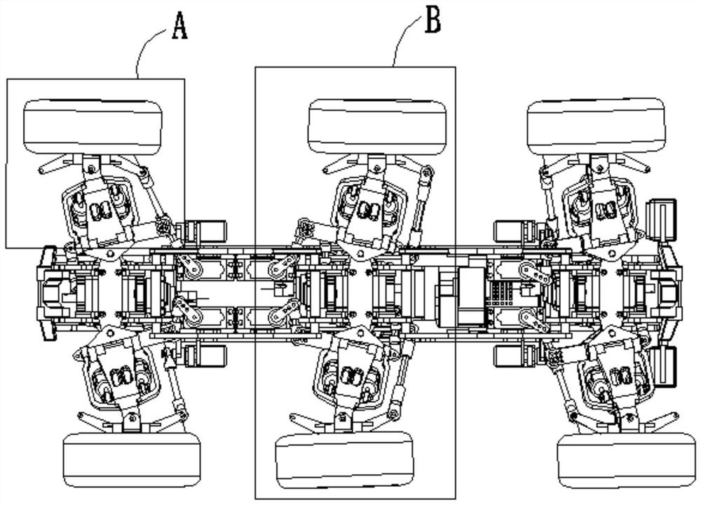
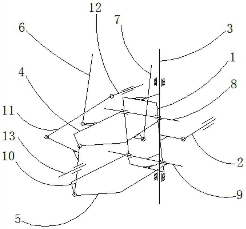
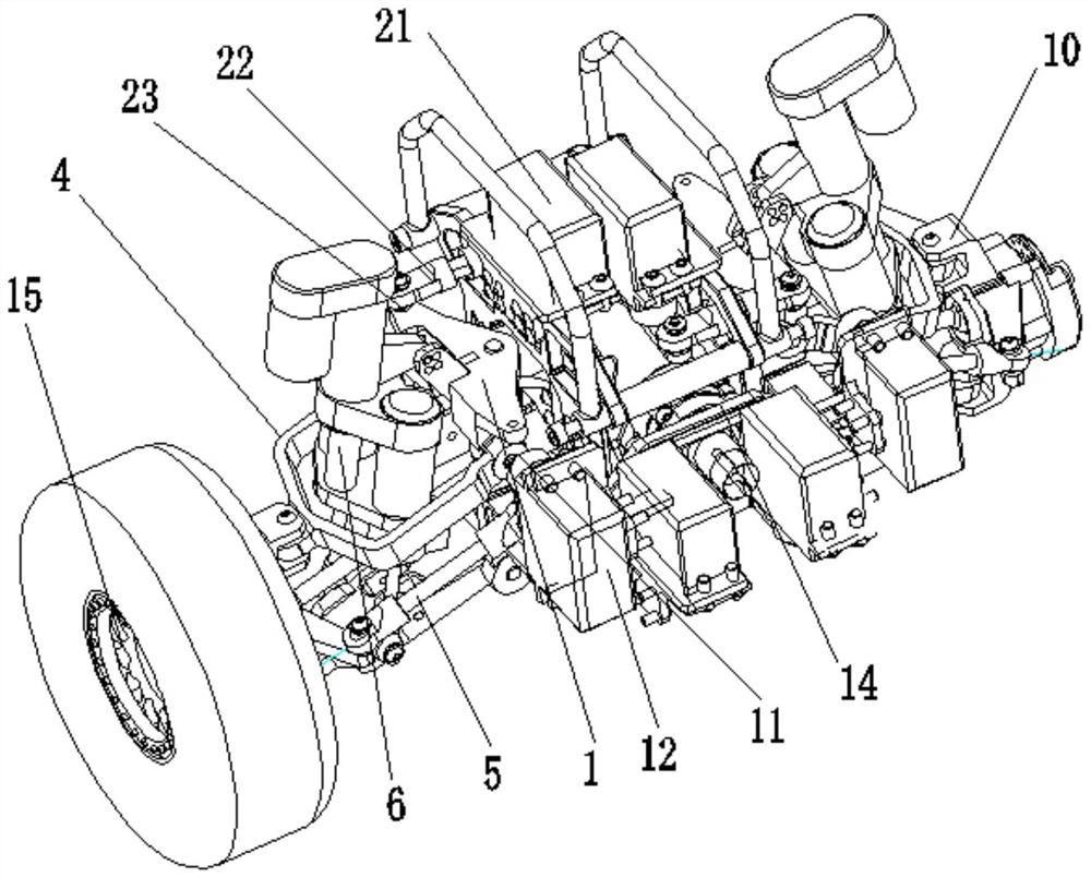
[0042] like figure 2 As shown, the embodiment of the present invention discloses a wheel-foot type robot suspension mechanism, which includes a front and rear swing part, an up and down movement part and a steering part;

[0043] The front and rear swing parts are movably installed on the main body of the robot chassis to swing back and forth;

[0044] The up and down movement part is movably installed on the front and rear swing parts for up and down movement; the up and down movement part extends out of the axle 13;

[0045] The steering part is hinged with the up and down moving part for steering movement.

[0046] In the present invention, the front and rear swinging part, the up and down moving part and the turning part are connected as a whole, which has the movement ability in three-dimensional space.

[0047] Specifically, the front and rear swing parts include a swing frame 1 and a first swing actuator 2; the swing frame 1 is installed on the robot chassis body thr...

Embodiment 2

[0060] like figure 2 As shown, the embodiment of the present invention discloses a wheel-foot type robot suspension mechanism, which includes a front and rear swing part, an up and down movement part and a steering part;

[0061] The front and rear swing parts are movably installed on the main body of the robot chassis to swing back and forth;

[0062] The up and down movement part is movably installed on the front and rear swing parts for up and down movement; the up and down movement part extends out of the axle 13;

[0063] The steering part is hinged with the up and down moving part for steering movement.

[0064] In the present invention, the front and rear swinging part, the up and down moving part and the turning part are connected as a whole, which has the movement ability in three-dimensional space.

[0065] Specifically, such as Figure 5 As shown, the steering part includes a second steering knuckle 101, a second steering tie rod 102, a steering drive rod 103 an...


PUM


Abstract

The invention discloses a wheel-foot type robot suspension mechanism, an axle module and a chassis. The suspension mechanism comprises a front-back swinging part, an up-down moving part and a steering part. The front-back swinging part is movably mounted on the robot chassis main body to swing front and back; the up-down moving part is movably mounted on the front-back swinging part to move up and down; the up-down moving part extends out of a wheel shaft; and the steering part is hinged with the up-down moving part to do steering motion. The axle module comprises two suspension mechanisms, and the two suspension mechanisms are symmetrically connected into a whole. The chassis comprises at least two axle modules, and the multiple axle modules are connected into a whole. The whole formed by connecting the front-back swinging part, the up-down moving part and the steering part has the moving capacity of a three-dimensional space, and compatibility of the high-speed running capacity and the cross-country maneuvering capacity of the wheel type robot can be achieved.

Description

technical field [0001] The invention relates to the technical field of robot mechanisms, and more specifically relates to a wheel-foot type robot suspension mechanism, an axle module and a chassis. Background technique [0002] Wheel-footed robots (wheel-legged robots) are a branch of current robots. The general structure is to add wheels to the end of the legs of the wheel-footed robot, so as to realize the combination of fast movement and footed walking, and can have some characteristics of both wheeled robots and footed robots. [0003] However, the structure of most wheel-footed robots is only a simple combination. This simple combination does not change the leg structure of the legged robot. Because the multi-body connection structure of the legged robot determines that its natural structural stiffness is insufficient, so It cannot travel at high speeds while performing wheeled movements. [0004] Therefore, it is an urgent problem for those skilled in the art to prov...

Claims


Application Information

Patent Timeline
Patent Type & Authority Applications(China)
IPC IPC(8): B62D57/028
CPCB62D57/028
Inventor 陈建王涛吴浩
Owner 陈晓妮
Learn More