Eureka AIR delivers breakthrough ideas for toughest innovation challenges, trusted by R&D personnel around the world.

Vertical cavity surface emitting laser array and preparation method thereof

A vertical cavity surface emission, laser array technology, applied in the field of lasers, can solve the problem that the consistency of the channel morphology of the light-emitting point cannot be guaranteed.

Active Publication Date: 2021-07-09
VERTILITE CO LTD
View PDF11 Cites 0 Cited by
  • Summary
  • Abstract
  • Description
  • Claims
  • Application Information

AI Technical Summary

Problems solved by technology

If it is expected to further reduce the pitch of the light-emitting units, if the width of the channel is directly reduced, since the limit of the photolithography process and dry etching process has been approached, the consistency of the channel morphology of different light-emitting points generated can no longer be achieved. ensure

Method used


Image

  • Vertical cavity surface emitting laser array and preparation method thereof
  • Vertical cavity surface emitting laser array and preparation method thereof
  • Vertical cavity surface emitting laser array and preparation method thereof

Examples


Embodiment Construction

[0066] The present invention will be further described in detail below in conjunction with the accompanying drawings and embodiments. It should be understood that the specific embodiments described here are only used to explain the present invention, but not to limit the present invention. In addition, it should be noted that, for the convenience of description, only some structures related to the present invention are shown in the drawings but not all structures.

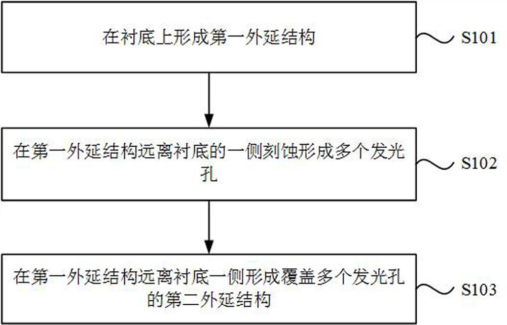
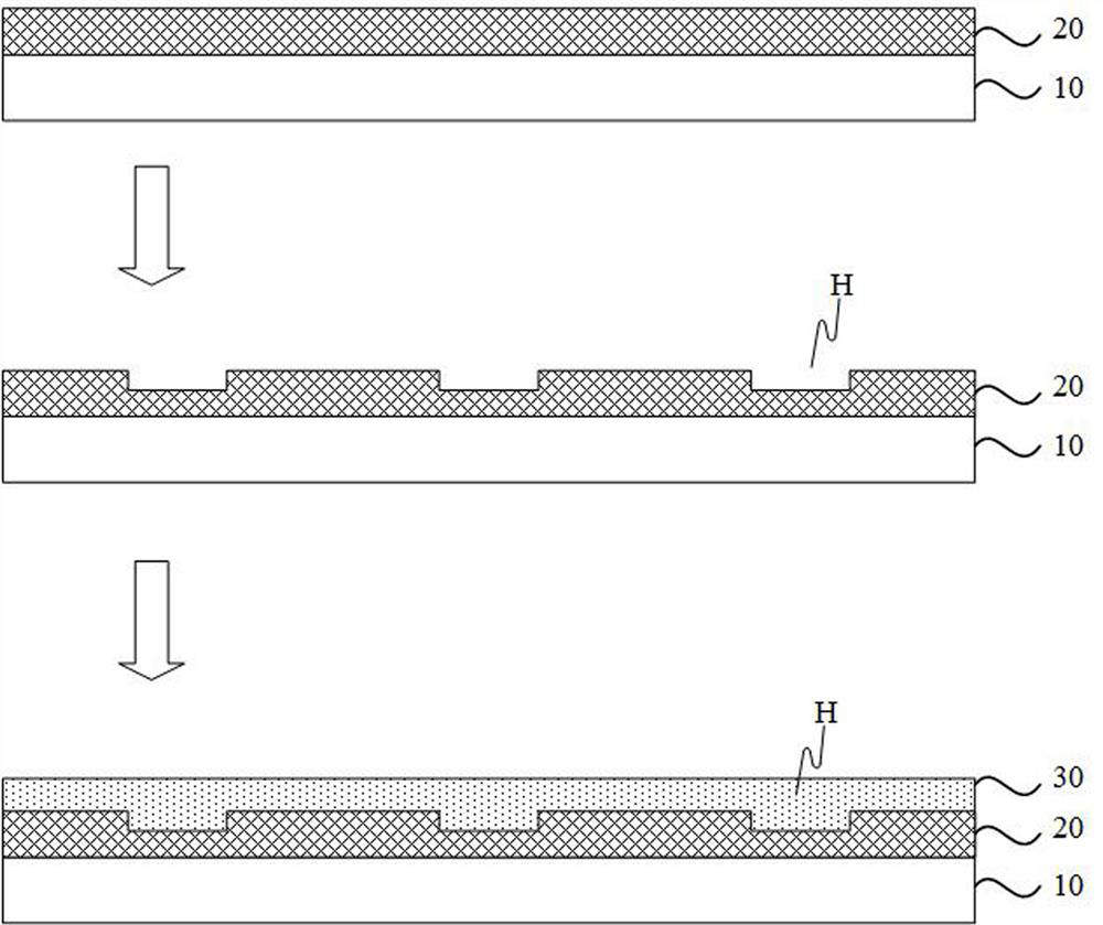
[0067] figure 1 A flow chart of the first method for fabricating a vertical cavity surface emitting laser array provided by an embodiment of the present invention, figure 2 For the preparation process diagram of the first vertical cavity surface emitting laser array provided by the embodiment of the present invention, refer to figure 1 and figure 2 , the preparation method of the vertical cavity surface emitting laser array provided by the embodiment of the present invention is used to prepare the vertical cav...


PUM


Abstract

The embodiment of the invention provides a vertical cavity surface emitting laser array and a preparation method thereof, which relate to the technical field of lasers. The vertical cavity surface emitting laser array comprises a plurality of vertical cavity surface emitting lasers. The preparation method comprises the following steps of forming a first epitaxial structure on a substrate, etching one side, far away from the substrate, of the first epitaxial structure to form a plurality of light emitting holes, and forming a second epitaxial structure covering the plurality of light emitting holes on one side, far away from the substrate, of the first epitaxial structure. The embodiment of the invention provides a vertical cavity surface emitting laser array and a preparation method thereof, which aim to realize that no mesa structure is formed, so that adjacent vertical cavity surface emitting lasers can be continuously connected, the distance between two adjacent vertical cavity surface emitting lasers is reduced, and the setting density of the vertical cavity surface emitting lasers in the vertical cavity surface emitting laser array is increased.

Description

technical field [0001] The invention relates to laser technology, in particular to a vertical cavity surface emitting laser array and a preparation method thereof. Background technique [0002] At present, in the application scenarios of many smart devices such as 3D sensing (mobile phone, payment, security, etc.), vehicle sensing, and medical treatment, there is a huge market demand for vertical cavity surface emitting laser arrays, and its device density And size miniaturization also put forward higher requirements. In the existing VCSEL array manufacturing, in order to increase the device density, it is usually achieved by increasing the number of light-emitting points and reducing the spacing. However, due to the limitation of the current semiconductor manufacturing process level, the gap between two adjacent light-emitting units There is still some difficulty in further reducing the width of the track. For the existing arrangement form, the distance between the edges ...

Claims


Application Information

Patent Timeline
Patent Type & Authority Applications(China)
IPC IPC(8): H01S5/30H01S5/32H01S5/42H01S5/183
CPCH01S5/183H01S5/30H01S5/32H01S5/426
Inventor 梁栋张成刘嵩
Owner VERTILITE CO LTD
Why Eureka
Eureka Blog
Learn More