Wet flue gas source heat pump system capable of controlling input flue gas pressure

A wet flue gas and flue gas technology, applied in the field of new wet flue gas source heat pump, can solve the problems of poor utilization effect of waste heat, complicated equipment composition, and reduction of heat exchange temperature difference, etc., to reduce the generation probability and improve the efficiency of water and heat recovery. Effect

Active Publication Date: 2021-07-09
SHANDONG UNIV
View PDF17 Cites 5 Cited by
  • Summary
  • Abstract
  • Description
  • Claims
  • Application Information

AI Technical Summary

Problems solved by technology

[0003] In recent years, there have been a lot of research and achievements on the utilization of flue gas waste heat and the recovery process of water vapor, which can be mainly divided into the following three categories: one is the indirect heat exchange process, such as the patent: "a pressurized control type flue gas Channel waste heat recovery system" (CN201611073039.1), "A wet-process integrated purification system and method for flue gas waste heat recovery" (CN201710001638.0), "A wet-process desulfurization and whitening device for flue gas" (CN201810302033.X), "An air compressor dehumidification and production increase device based on supercharger waste heat recovery" (CN201920432998.0) adopts the traditional heat exchange form of indirect contact between flue gas and heat exchange medium. This method is relatively mature in technology and has a wide range of applications. But the disadvantage is that due to the indirect heat exchange, affected by the temperature difference at the cold end between the flue gas and the heat-absorbing medium, the heat transfer is small, and the outlet temperature of the heat-absorbing medium is lower, which is generally about 5 lower than the flue gas outlet temperature of the heat exchanger. ℃, the outlet temperature is low, which limits its subsequent heat utilization scenarios, and the waste heat utilization effect is poor
The second is a direct heat exchange process, such as patents: "A water spray direct cooling flue gas condensation system and method" (CN201810938098.3), "An integrated device for whitening elimination and purification" (CN201910832971.5), "A Flue gas purification method for flue gas purification" (CN201911196365.5) uses direct contact between flue gas and heat exchange medium for heat exchange. This form can effectively reduce the heat exchange temperature difference, and the cost of the contact reactor is low. The wet flue gas at the outlet is still in a saturated state, and only the sensible heat energy of the flue gas can be used, and the extraction and utilization of water vapor and its latent heat cannot be realized. The impurity components in the flue gas will pollute the recovery medium
However, the equipment composition of the heat pump system is relatively complicated, and the initial investment cost is relatively high. Among them, the closed heat pump system belongs to the form of indirect heat exchange, which can only reduce the wet flue gas to a saturated state at the corresponding temperature, and cannot further condense and extract water vapor; The absorption solution of the heat pump system directly contacts and reacts with the flue gas. Pollutant components and impurity particles in the flue gas will enter the absorption solution to cause solution pollution, which will lead to scaling or blockage in the pipeline, and the system reliability is poor.

Method used


Image

  • Wet flue gas source heat pump system capable of controlling input flue gas pressure
  • Wet flue gas source heat pump system capable of controlling input flue gas pressure
  • Wet flue gas source heat pump system capable of controlling input flue gas pressure

Examples


Embodiment Construction

[0029] The specific embodiments of the present invention will be described in detail below in conjunction with the accompanying drawings.

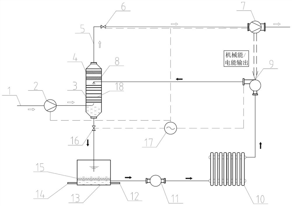
[0030] figure 1 A wet flue gas source heat pump system for water collection, waste heat recovery and pollutant removal is shown. Such as figure 1 As shown, the system includes a flue gas inlet 1, a heat exchanger 3, a flue gas pressure regulating device 2, pressure control valves 6 and 16, a turbine 7, a circulating water tank 13 and a user-end heat output device 10, the flue gas inlet 1 is connected to the flue gas pressure regulating device 2, the flue gas pressure regulating device 2 is connected to the heat exchanger 3, the flue gas outlet at the upper end of the heat exchanger 3 is connected to the turbine 7, and the first pressure control is set on the pipeline between the flue gas outlet 5 and the turbine 7 Valve 6, the hot water outlet at the lower end of the heat exchanger 3 is connected to the circulating water tank 13, a secon...


PUM


Abstract

The invention provides a wet flue gas source heat pump system capable of controlling input flue gas pressure. The system comprises a flue gas inlet, a heat exchanger, a flue gas pressure adjusting device, a pressure control valve, a controller, a turbine, a circulating water tank and a user side heat output device. A temperature and / or pressure sensor is mounted on a flue gas outlet at the upper portion of the heat exchanger and used for detecting the temperature and / or pressure of discharged flue gas. The flue gas pressure adjusting device and the temperature and / or pressure sensor are in data connection with the controller, the controller automatically adjusts the power of the flue gas pressure adjusting device according to the detected temperature and / or pressure, and the pressure adjusting valve and the temperature and / or pressure sensor are in data connection with the controller. The controller automatically adjusts the control threshold value of the pressure adjusting valve according to the detected temperature and / or pressure. The power of the flue gas pressure adjusting device and the threshold value of the pressure adjusting valve can be controlled according to the flue gas temperature and pressure of the outlet of the heat exchanger, it can be guaranteed that the temperature and flow of a hot water outlet of the heat exchanger meet the heat supply requirement, then parameters of flue gas entering the turbine are changed, and meanwhile use of electric energy of equipment in the system is met.

Description

technical field [0001] The invention belongs to the technical fields of heat exchange, waste heat utilization and environmental protection, and relates to a novel wet smoke gas source heat pump for water collection, waste heat recovery and pollutant removal. Background technique [0002] Boilers, kilns, blast furnaces, gas furnaces, etc. need to be equipped with flue gas and tail gas treatment devices. Limestone-gypsum wet desulfurization technology is mainly used for desulfurization. The desulfurization slurry is circulated and sprayed into the desulfurization absorption tower. 2 A gas-liquid contact reaction is carried out. During the spraying process, the water in the slurry is heated and evaporated by the flue gas, and the flue gas at the outlet of the absorption tower will reach the dew point temperature corresponding to the saturated state, which is generally about 50°C, and the mass fraction of water vapor is about 10-15%. Taking a 600MW coal-fired boiler as an examp...

Claims


Application Information

Patent Timeline
Patent Type & Authority Applications(China)
IPC IPC(8): F28C1/00F28F27/00B01D53/78B01D53/40B01D53/96C02F9/04F01D15/10
CPCF28C1/00F28F27/00B01D53/78B01D53/40B01D53/96C02F1/001C02F1/00F01D15/10F28C2001/006B01D2258/0283
Inventor 董勇王晓哲刘雷崔琳
Owner SHANDONG UNIV
Why Eureka
Try Eureka