Management system of environmental sanitation vehicle

A management system and vehicle technology, applied in the field of sanitation vehicle management system, to achieve recycling, improve cooling effect, and uniform cooling

Inactive Publication Date: 2021-07-09
厦门庆丰年网络科技有限公司
View PDF19 Cites 2 Cited by
  • Summary
  • Abstract
  • Description
  • Claims
  • Application Information

AI Technical Summary

Problems solved by technology

[0003] The sanitation vehicle needs to be managed centrally during use. The existing technology manages the maintenance and delivery of the vehicle through the management system. The existing management system usually includes the shell and the equipment installed inside the shell. Due to the use of the system Environmental impact, usually the system will set the shock absorption setting, and the shock absorption process of the prior art simply uses elastic parts to absorb the vibration energy, but does not collect and reuse it. Now we provide a sanitation vehicle management system to solve the technical problem

Method used


Image

  • Management system of environmental sanitation vehicle
  • Management system of environmental sanitation vehicle
  • Management system of environmental sanitation vehicle

Examples


Embodiment 1

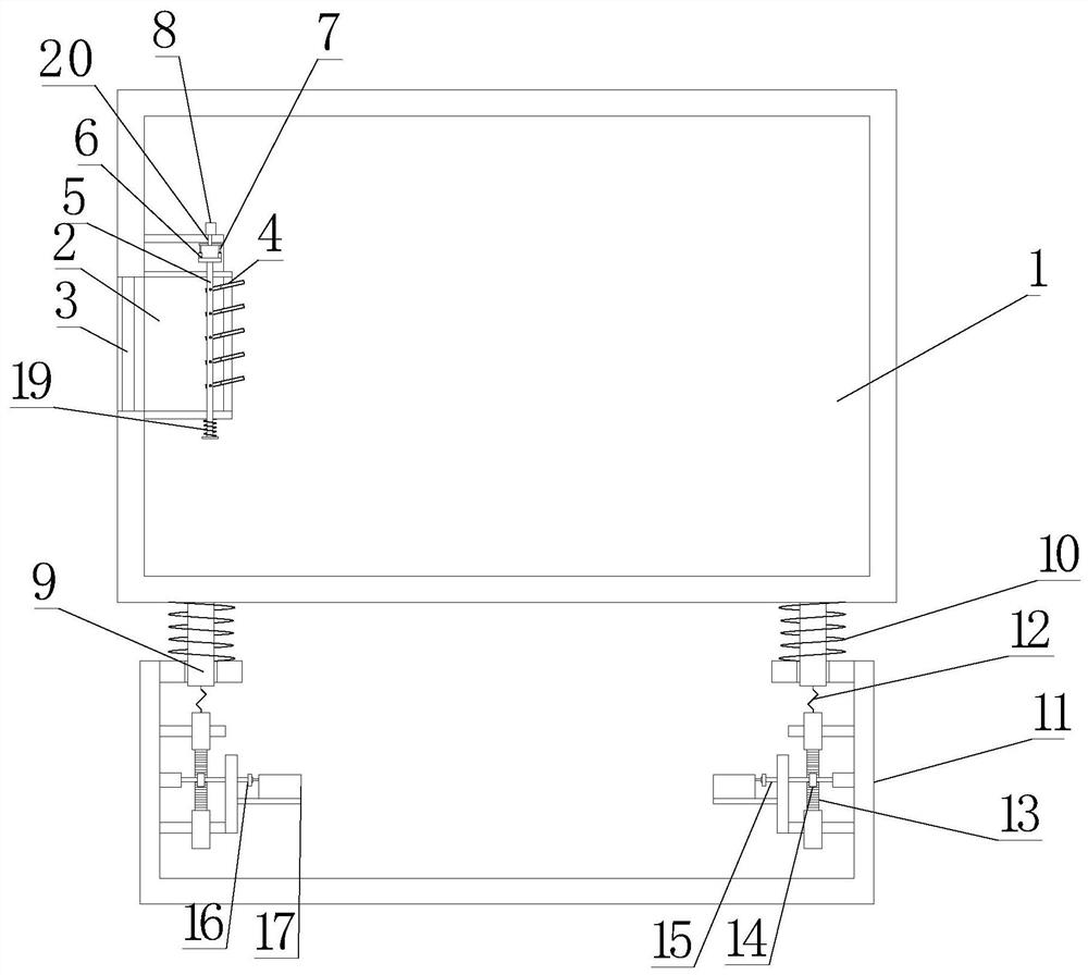
[0027] see Figure 1~2 , in Embodiment 1 of the present invention, it is a structural diagram of a sanitation vehicle management system provided by the embodiment of the present invention, including: a casing 1 and a base 11, wherein the interior of the casing 1 is provided for installing control components; The housing 1 is installed on the base 11;

[0028] The casing 1 is provided with an air inlet 2, and the outlet of the air inlet 2 is provided with a plurality of reciprocating swing leaves 4 in an array, which are used to allow the cooling air to swing and change directions to enter the inside of the casing 1; Both sides of the bottom of the housing 1 are fixedly equipped with connecting rods 9, the connecting rods 9 pass through the sliding holes on the base 11, and the connecting rods 9 are elastically arranged on the base 11 for shock absorption; the connecting rods 9 It is connected with the slide bar 13 which is slid up and down on the base 11. Both sides of the sl...

Embodiment 2

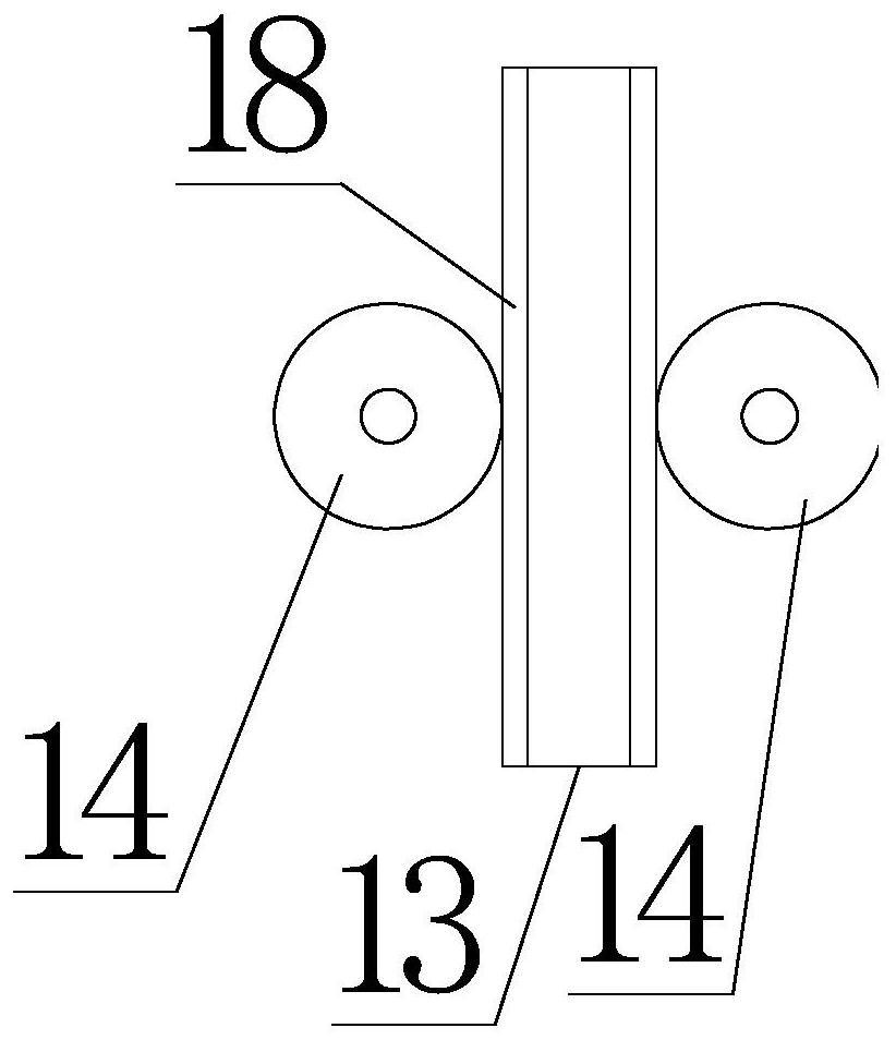
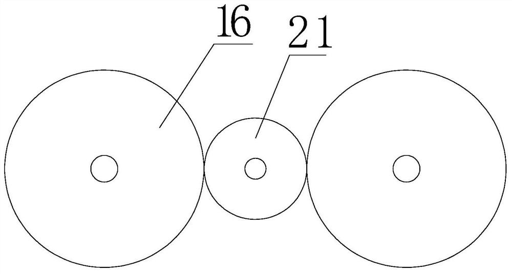
[0031] see Figure 1~4 , the main difference between this embodiment 2 and embodiment 1 is that, as a preferred embodiment of the present invention, the transmission assembly includes two installation shafts 15 and two first transmission wheels 16, wherein the one-way The wheels 14 are respectively fixedly sleeved on the installation shaft 15, and the two installation shafts 15 are respectively fixedly sleeved at the end away from the one-way wheel 14, and the two first transmission wheels 16 are respectively meshed with the second transmission wheel 21, and the first The two drive wheels 21 are connected to the input end of the generator 17. Specifically, when the slide bar 13 moves downward, the rack 18 on one side drives the one-way wheel 14 on one side to rotate, and the one-way wheel 14 on one side passes through the installation shaft. 15 drives a first transmission wheel 16 to rotate, the first transmission wheel 16 provides power for the rotation of the generator 17 th...


PUM


Abstract

The invention is applicable to the technical field of vehicle management equipment, and provides a management system of an environmental sanitation vehicle. The management system comprises a shell and a base, wherein a control part is arranged in the shell; the shell is arranged on the base; an air inlet is formed in the shell; a plurality of swinging blades which swing in a reciprocating manner are arranged at an outlet of the air inlet in an array manner, so that cooling air can swing and change the direction to enter the shell; connecting rods are fixedly arranged on two sides of the bottom of the shell; the connecting rods penetrate through sliding holes in the base; the connecting rods are elastically arranged on the base and are used for damping; the connecting rods are connected with a sliding rod which is arranged on the base in an up-down sliding manner; racks are fixedly arranged on two sides of the sliding rod; the racks on the two sides are respectively meshed with two one-way wheels; and the two one-way wheels are in transmission connection with a generator through a transmission assembly. According to the management system disclosed by the invention, vibration energy is recycled, the interior of the shell can be comprehensively cooled, and the cooling is uniform.

Description

technical field [0001] The invention relates to the technical field of vehicle management equipment, in particular to a management system for sanitation vehicles. Background technique [0002] Sanitation vehicle Sanitation vehicle is a special vehicle used for urban tidying and cleaning. [0003] The sanitation vehicle needs to be managed centrally during use. The existing technology manages the maintenance and delivery of the vehicle through the management system. The existing management system usually includes the shell and the equipment installed inside the shell. Due to the use of the system Environmental impact, usually the system will set the shock absorption setting, and the shock absorption process of the prior art simply uses elastic parts to absorb the vibration energy, but does not collect and reuse it. Now we provide a sanitation vehicle management system to Solve the technical problem. Contents of the invention [0004] The purpose of the present invention i...

Claims


Application Information

Patent Timeline
Patent Type & Authority Applications(China)
IPC IPC(8): F03G7/08H05K7/20F16F15/067
CPCF03G7/08H05K7/20136F16F15/067
Inventor 朱健飞
Owner 厦门庆丰年网络科技有限公司
Why Eureka
Try Eureka