Protective barrier fixer for highway bridge construction
A technology for protective railings and highway bridges, applied in bridges, bridge parts, bridge construction, etc., can solve problems such as troublesome installation, troublesome disassembly and installation, artificial damage, etc., and achieve the effect of easy installation and disassembly, and easy fixing of protective railings
- Summary
- Abstract
- Description
- Claims
- Application Information
AI Technical Summary
Problems solved by technology
Method used
Image
Examples
no. 1 example
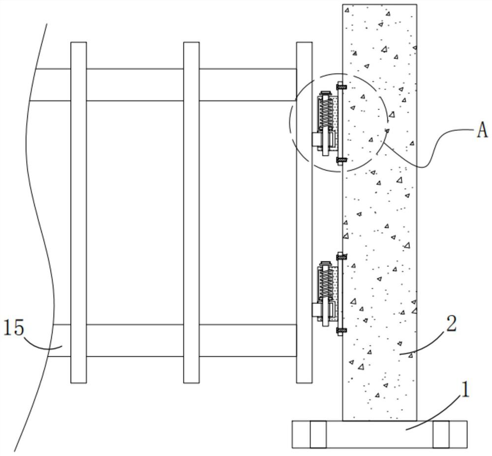
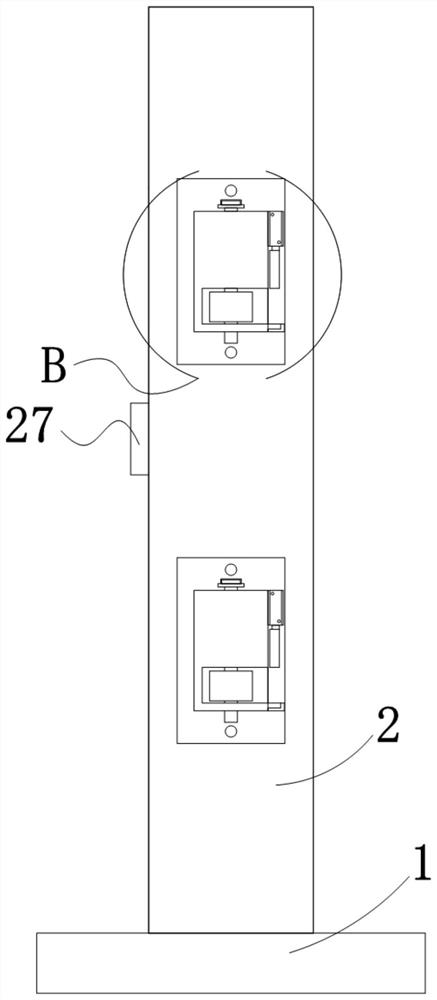
[0048] Please refer to Figure 1 to Figure 4 , in the first embodiment of the present invention, a kind of protective railing fixture for highway bridge construction comprises: the first installation block 1; Railing 2, railing 2 is arranged on the top of first installation block 1; Controller, controller is set On one side of the railing 2; two fixing mechanisms, the two fixing mechanisms are arranged on the railing 2.
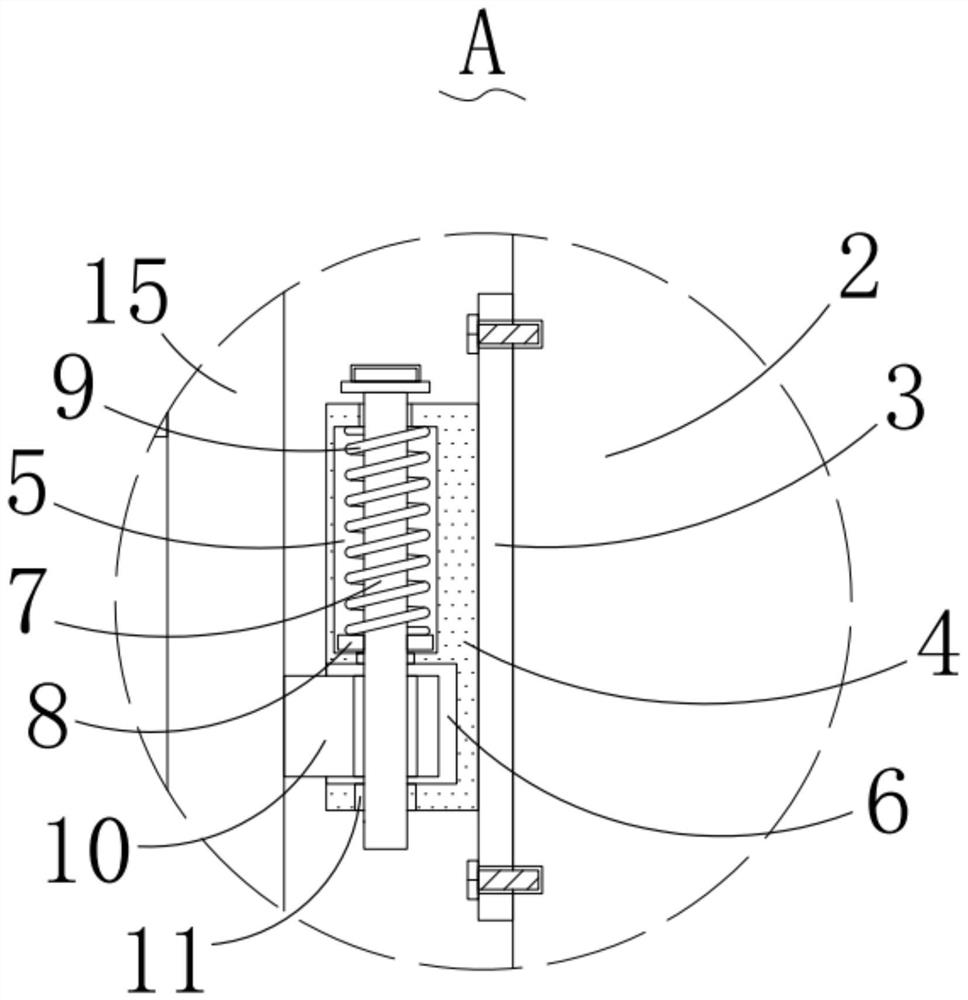
[0049] The fixing mechanism includes a second mounting block 3, a first fixing block 4, a cavity 5, a first groove 6, a sliding rod 7, a magnetic ring 8, a spring 9, a clamping block 10, a clamping hole 11, a cylinder 12, and a clamping plate 13 , the second fixed block 14, the second installed block 3 is arranged on the side outer wall of the railing 2, the first fixed block 4 is arranged on the side outer wall of the second installed block 3, and the cavity 5 is opened on the first fixed block 4 Above, the first groove 6 is opened on one side of the outer ...
no. 2 example
[0057] Based on the protective railing fixture for highway bridge construction provided in the first embodiment of the application, the second embodiment of the application proposes another protective railing fixture for highway bridge construction, and the second embodiment is only the first implementation Example As a further solution of the present invention, the implementation of the second embodiment will not affect the single implementation of the first embodiment.
[0058] The second embodiment of the present invention will be further described below in conjunction with the drawings and implementation methods
[0059] Please refer to Figure 4-Figure 8 , in the second embodiment of the present invention, a protective railing fixture for highway bridge construction further includes: a lighting mechanism, the lighting mechanism is arranged on the side of the railing 2 .
[0060] The lighting mechanism includes a second groove 16, the second groove 16 is opened on one sid...
no. 3 example
[0065] Based on the protective railing fixture for highway bridge construction provided in the second embodiment, the energy-saving lamp 25 does not perform lighting work during the daytime during specific use, but needs to be illuminated when there is construction work near the highway bridge at night or when construction vehicles pass by. , do not illuminate at other times, and when the vehicle breaks down or the line of sight is not good at night and collides with the guardrail 15, the fixed connection between the guardrails 15 will cause the greatest degree of vehicle accidents, but the above-mentioned embodiment passes the motor 17 and manual control The turn-on time of the energy-saving lamp 25 is not only inefficient, but also easily causes waste of energy. At the same time, it cannot effectively remind the vehicle at night, and effectively buffer the collision of the vehicle that has an accident. Therefore, in order to solve this problem, the energy-saving lamp 25 self-...
PUM
 Abstract
Description
Claims
Application Information
 - R&D
- Intellectual Property
- Life Sciences
- Materials
- Tech Scout
- Unparalleled Data Quality
- Higher Quality Content
- 60% Fewer Hallucinations
Browse by: Latest US Patents, China's latest patents, Technical Efficacy Thesaurus, Application Domain, Technology Topic, Popular Technical Reports.
© 2025 PatSnap. All rights reserved.Legal|Privacy policy|Modern Slavery Act Transparency Statement|Sitemap|About US| Contact US: help@patsnap.com


