High-precision pneumatic power head

A power head and high-precision technology, applied in the field of power heads, can solve the problems of scrapped processed products, increased production costs, and offset of micro-product processing positions, etc., and achieve the effect of stable air kinetic energy and high drill speed

Active Publication Date: 2021-07-09
ZHEJIANG QUNZHEN TECH
View PDF7 Cites 0 Cited by
  • Summary
  • Abstract
  • Description
  • Claims
  • Application Information

AI Technical Summary

Problems solved by technology

[0002] The power head is a power part that can realize the main movement and feed movement, and has automatic workpiece circulation. At present, the micro power head is used for the processing of mobile phone circuit boards. The micro power head needs to process the circuit board mounting holes smaller than the hair, so The processing accuracy requirements for the power head are very high; the existing miniature power heads generally use brushless motors, brushed motors or other motors as the driving kinetic energy, and the output shaft of the motor drives the power head drill to rotate the processed products. The vibration will affect the concentricity of the power head drill bit, resulting in the offset of the processing position of the power head drill bit for processing micro products, resulting in the scrapping of the processed products and increasing the production cost

Method used


Image

  • High-precision pneumatic power head
  • High-precision pneumatic power head
  • High-precision pneumatic power head

Examples


Embodiment Construction

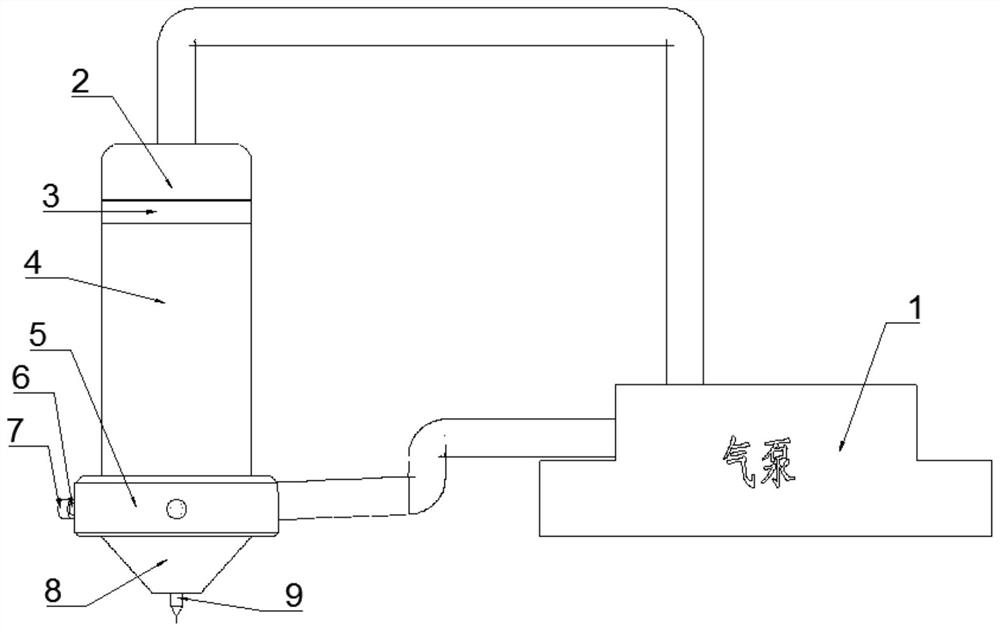
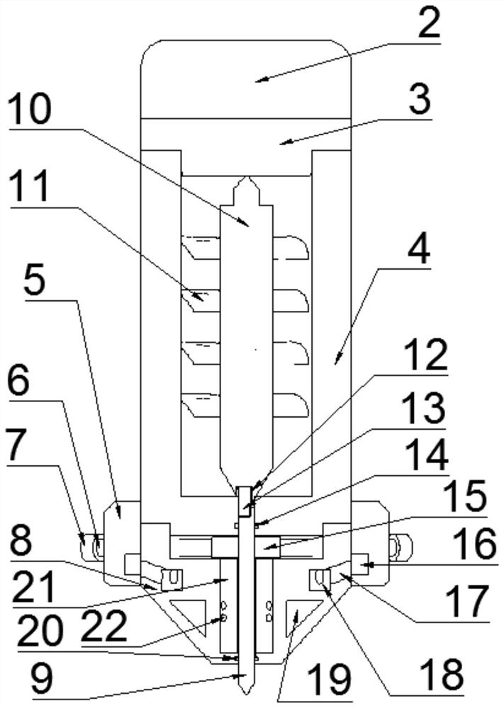
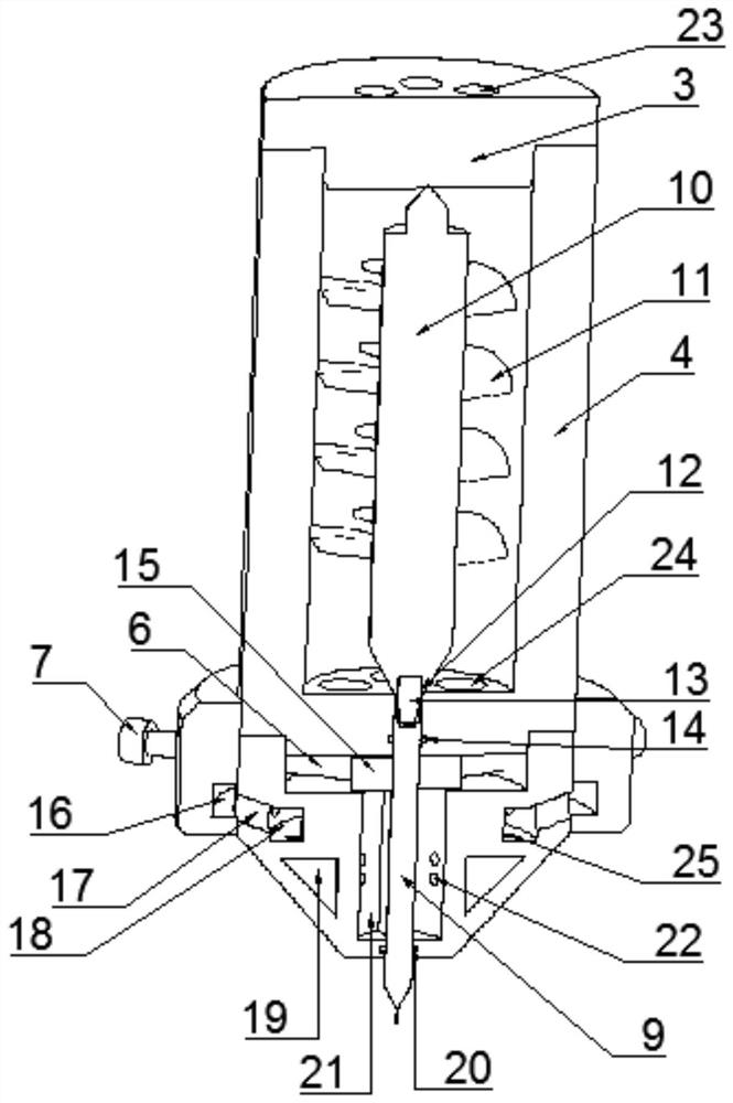
[0025] Such as Figure 1 to Figure 3 As shown, in the specific present embodiment, a high-precision pneumatic power head includes a power bushing 4, a driving assembly arranged in the power bushing 4, a drill assembly arranged at the bottom of the driving assembly, and the driving assembly includes a power shaft 10. Coupling 13, upper cover 3, air cover 2 and air pump 1. Upper cover 3 is fixedly connected to the top of power bushing 4. Upper cover 3 is provided with a plurality of ventilation holes 23. Air cover 2 is located at the top of upper cover 3. , the air pump 1 is connected to the air cover 2 through a pipeline, the power shaft 10 is built in the power shaft sleeve 4, the shaft body of the power shaft 10 is cylindrical, and both ends of the shaft are conical. The impeller 11, the middle part of the bottom end of the power shaft sleeve 4 is provided with a connecting through hole, the upper end of the power shaft 10 is inserted into the middle inner wall of the upper c...


PUM


Abstract

The invention discloses a high-precision pneumatic power head. The power head is characterized in that the high-precision pneumatic power head comprises a power shaft sleeve, a driving assembly arranged in the power shaft sleeve and a drill bit assembly arranged at the bottom of the driving assembly, wherein the driving assembly comprises a power shaft, a coupler, an upper cover, an air cover and an air pump, the upper cover is fixedly connected with the top end of the power shaft sleeve, a plurality of vent holes are formed in the upper cover, the air cover is located at the top end of the upper cover, the air pump is connected with the air cover by means of a pipeline, the power shaft is arranged in the power shaft sleeve, a shaft body of the power shaft is cylindrical, the two ends of the shaft are conical, a plurality of axially-arranged impellers are arranged on the outer wall of the power shaft, a connecting through hole is formed in the middle of the bottom end of the power shaft sleeve, the upper end of the power shaft is inserted into the inner wall of the middle of the upper cover, and the lower end of the power shaft is inserted into the connecting through hole. The power head is driven by utilizing air kinetic energy, and air pressure near a drill bit rod part is stable by utilizing multi-stage channels in a drill bit sleeve, so that a power head drill bit works stably, and a product processing effect is good.

Description

technical field [0001] The invention relates to the field of power heads, in particular to a high-precision pneumatic power head. Background technique [0002] The power head is a power part that can realize the main movement and feed movement, and has automatic workpiece circulation. At present, the micro power head is used for the processing of mobile phone circuit boards. The micro power head needs to process the circuit board mounting holes smaller than the hair, so The processing accuracy requirements for the power head are very high; the existing micro power heads generally use brushless motors, brushed motors or other motors as the driving kinetic energy, and the output shaft of the motor drives the power head drill to rotate the processed product, but the motor produces The vibration will affect the concentricity of the power head drill bit, causing the machining position of the power head drill bit to process micro products to shift, resulting in the scrapping of pr...

Claims


Application Information

Patent Timeline
Patent Type & Authority Applications(China)
IPC IPC(8): B26F1/16B26D5/12H05K3/00
CPCB26F1/16B26D5/12H05K3/0047B26F2210/08Y02P70/10
Inventor 黄长峰金建成
Owner ZHEJIANG QUNZHEN TECH
Why Eureka
Try Eureka