
An intelligent bionic prosthetic hand

A prosthetic hand and intelligent technology, applied in the field of bionic hands, can solve the problems of high cost, less freedom of fingers, narrow range of objects, etc., and achieve the effect of increasing friction, good anti-slip effect, and flexible operation

Active Publication Date: 2022-03-29
BEIJING INSTITUTE OF TECHNOLOGYGY
View PDF6 Cites 0 Cited by
  • Summary
  • Abstract
  • Description
  • Claims
  • Application Information

AI Technical Summary

Problems solved by technology

[0003] The existing intelligent prosthetic hand drive method mainly uses gears with complex gear set transmission structure to realize various hand movements. Although it has high control accuracy, it also has a high failure rate, heavy weight and high cost. The problem is not conducive to the promotion and application of prosthetic hands
[0004] Chinese patent document CN110731839A discloses a prosthetic hand, which adopts the ring finger, little finger and middle finger to be driven by the same motor. Although the number of driving motors is reduced, it is beneficial to reduce the size and weight of the palm, but its circuit board is arranged in the rotating wrist. Increased the size of the rotating wrist, which in turn increases the overall hand height
At the same time, the three fingers share the same drive motor, and the degrees of freedom of each finger are small, which is not convenient for precise grasping of finer objects, and the range of objects suitable for grasping is relatively narrow

Method used


Image

  • An intelligent bionic prosthetic hand
  • An intelligent bionic prosthetic hand
  • An intelligent bionic prosthetic hand

Examples


Embodiment Construction

[0050] The technical solutions of the present invention will be clearly and completely described below with reference to the accompanying drawings. Obviously, the described embodiments are a part of the embodiments of the present invention, but not all of the embodiments. Based on the embodiments of the present invention, all other embodiments obtained by those of ordinary skill in the art without creative efforts shall fall within the protection scope of the present invention.

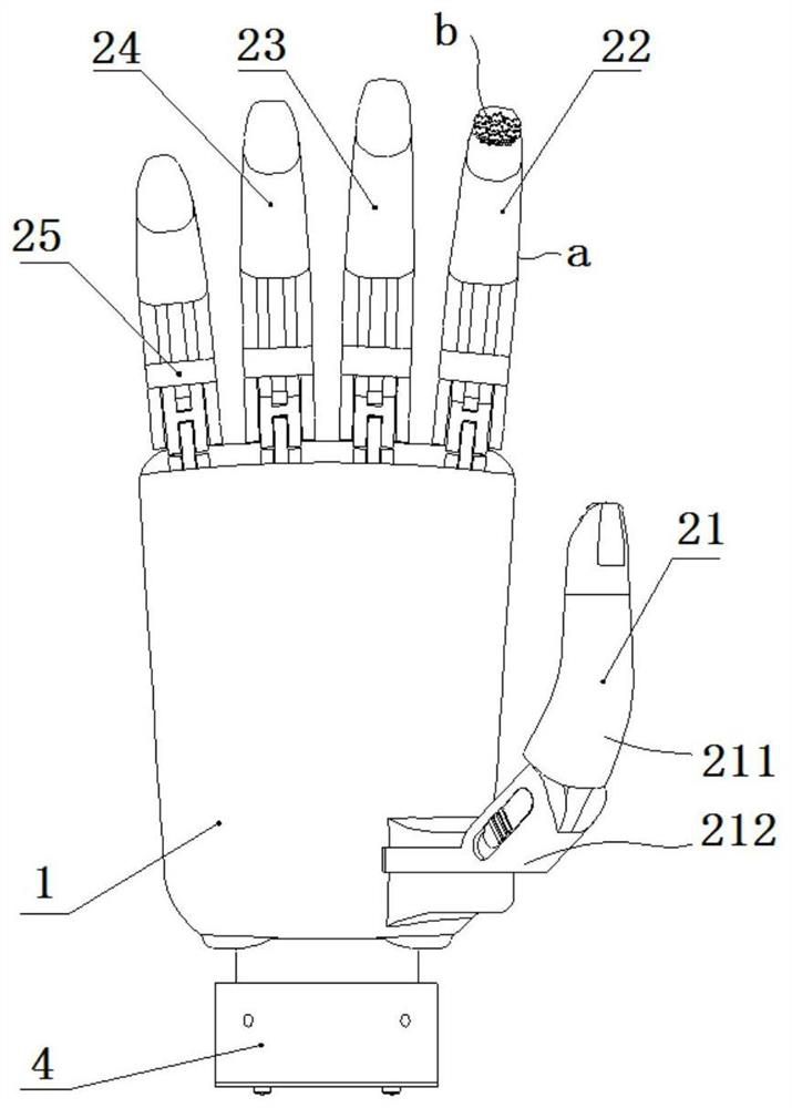
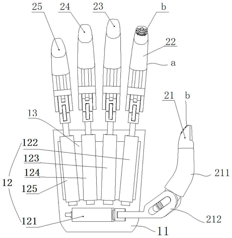
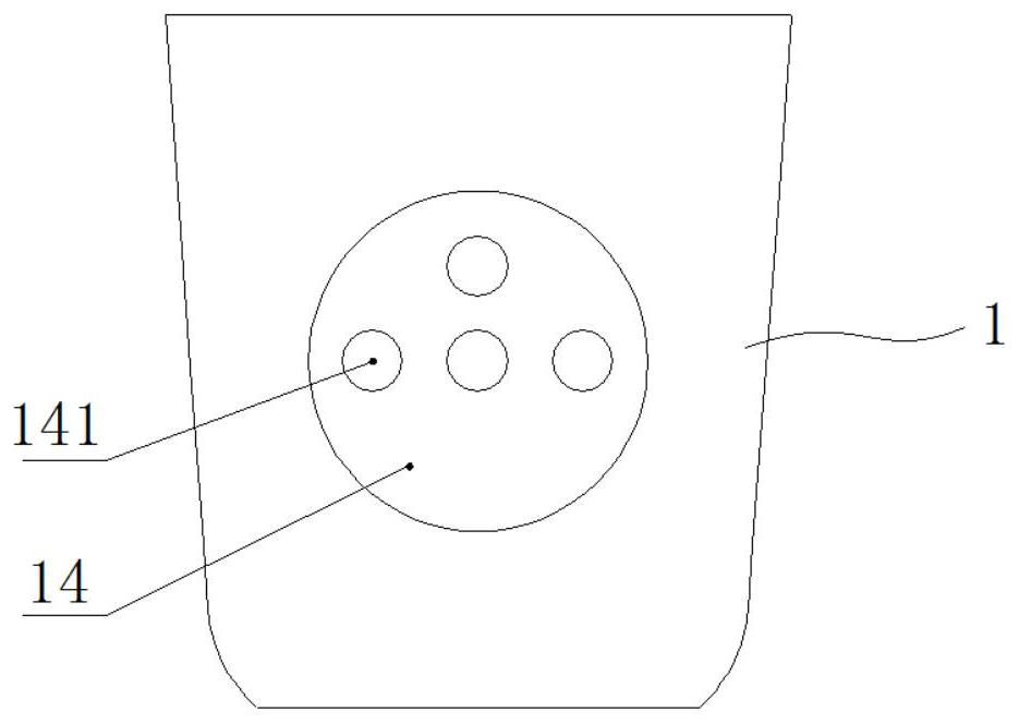
[0051] like figure 1 and figure 2 As shown, the present invention provides a prosthetic hand, which includes a palm assembly 1 and a finger assembly 2, wherein the finger assembly 2 at least includes a thumb assembly 21 and an index finger assembly 22, and the palm assembly 1 includes a housing 11 and a driving device 12. A cavity is formed in the body 11, and the driving device 12 is arranged in the cavity, and forms an independent driving connection with each finger assembly 2 located at the upper...


PUM


Abstract

The invention discloses an intelligent bionic prosthetic hand, which includes a palm assembly and a finger assembly. The finger assembly includes at least a thumb assembly and a forefinger assembly. The palm assembly includes a housing and a driving device. A cavity is formed in the housing, and the driving device is arranged in the cavity. Indoors, the palm assembly is also provided with a circuit board electrically connected to the drive device. The drive device is a linear motor, which forms an independent drive connection with each finger in the finger assembly connected to the upper end of the housing; the thumb assembly includes the upper thumb joint and the thumb joint. The lower joint, the upper joint of the thumb and the lower joint of the thumb form a rotating connection through a rotating shaft. The lower end of the upper joint of the thumb is arc-shaped, and there are multiple sawtooth structures on the arc-shaped end surface, corresponding to the arc-shaped end surface of the upper thumb joint There is an elastic jacking mechanism at the end surface of the lower thumb joint, and the jacking mechanism cooperates with the sawtooth structure to manually control the bending angle of the upper thumb joint. The invention realizes the precise grasping and pinching of the prosthetic hand, and is suitable for a wider range of grasping objects.

Description

technical field [0001] The invention relates to the technical field of bionic hands, in particular to an intelligent bionic artificial limb hand. Background technique [0002] The control of the intelligent prosthetic hand mostly adopts the EMG control method, which uses the tiny EMG potential difference signal as the initial signal to control and manipulate various functions of the EMG prosthesis, so as to control the opening and closing of the prosthetic hand. [0003] The existing intelligent prosthetic hand driving method mainly uses a complex gear set transmission structure to realize various actions of the hand. Although it has high control accuracy, it has a high failure rate, heavy weight and high cost. It is not conducive to the promotion and application of prosthetic hands. [0004] Chinese patent document CN110731839A discloses a prosthetic hand, which adopts the ring finger, little finger and middle finger to be driven by the same motor. Although the number of d...

Claims


Application Information

Patent Timeline
Patent Type & Authority Patents(China)
IPC IPC(8): A61F2/58A61F2/70
CPCA61F2/586A61F2002/701
Inventor 田野胡宾宾李加良朱金营
Owner BEIJING INSTITUTE OF TECHNOLOGYGY
Learn More