Large floor mopping machine

A floor mopping machine and large-scale technology, which is applied in the direction of cleaning carpets, floors, machine parts, etc., can solve the problems of high vacuum pump power, high power consumption, and high noise of vacuum pumps, so as to reduce equipment costs, increase the area to be wiped, The effect of saving power and noise

Inactive Publication Date: 2021-07-09
SHENYANG SIASUN ROBOT & AUTOMATION
View PDF6 Cites 0 Cited by
  • Summary
  • Abstract
  • Description
  • Claims
  • Application Information

AI Technical Summary

Problems solved by technology

[0003] The basic structure of the traditional floor washing machine is that the front brush plate combines with clean water to scrub the ground, and the back is the suction rake. The curved suction rake collects the sewage and then pumps it up through the vacuum pump. The disadvantage of the traditional floor washing machine is that the sewage has to be pumped from the ground. It needs a lot of suction, so the power of the vacuum pump is very large, and it consumes a lot of power when it works. Moreover, the noise of the vacuum pump is huge when it is working, generally exceeding 70 decibels.

Method used


Image

  • Large floor mopping machine
  • Large floor mopping machine
  • Large floor mopping machine

Examples


Embodiment Construction

[0022] The present invention will be described in further detail below in conjunction with the accompanying drawings.

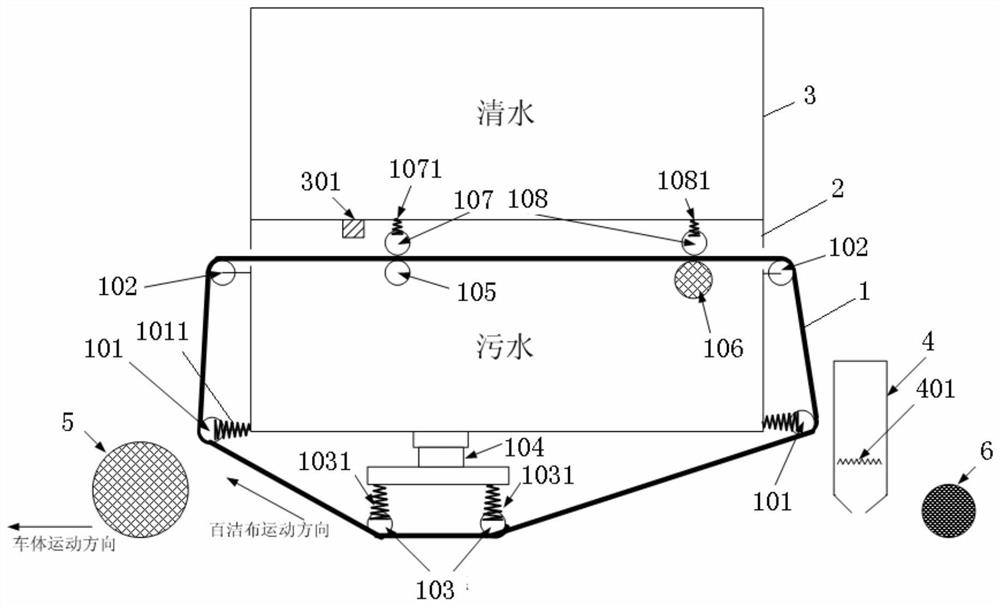
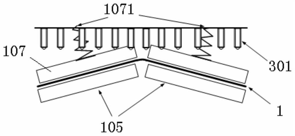
[0023] Such as Figure 1~3 As shown, the present invention comprises car body, water tank and cleaning cloth 1, and described water tank and cleaning cloth 1 are all arranged in the car body, and described water tank top forms clean water tank 3, and the bottom forms dirty water tank 2, and described dirty water tank 2 Fixed rollers 102 are arranged on the upper ends of both sides, and telescopic rollers 101 are arranged on the lower ends of both sides. A squeeze roller assembly and a driving roller 106 are arranged in the sewage tank 2, and the driving roller 106 is driven to rotate by a motor. The lower side of the sewage tank 2 is provided with a movable roller 103 and a lifting drive device 104 for driving the movable roller 103 to lift. Roller 101, then bypasses the movable roller 103 on the lower side of the sewage tank 2, then bypasses the telescopic ...


PUM


Abstract

The invention relates to the field of cleaning equipment, in particular to a large floor mopping machine which comprises a vehicle body, a water tank and cleaning cloth, wherein the water tank and the cleaning cloth are arranged in the vehicle body, a clean water tank is formed on the upper portion of the water tank, a sewage tank is formed on the lower portion of the water tank, fixed rollers are arranged at the upper ends of the two sides of the sewage tank, telescopic rollers are arranged at the lower ends of the two sides of the sewage tank, a wringing roller assembly and a driving roller are arranged in the sewage tank, a movable roller and a lifting driving device are arranged on the lower side of the sewage tank, after being output through the driving roller, the cleaning cloth firstly bypasses the fixed roller and the telescopic roller on the rear side of the sewage tank, then bypasses the movable roller on the lower side of the sewage tank, then bypasses the telescopic roller and the fixed roller on the front side of the sewage tank, and passes through the wringing roller assembly to form a closed ring, a nozzle is arranged on a partition plate between the clean water tank and the sewage tank, and the nozzle is arranged on the front side of the wringing roller assembly. The floor mopping machine saves more electricity, is lower in noise, increases the floor mopping area, and is particularly suitable for cleaning large indoor places.

Description

technical field [0001] The invention relates to the field of cleaning equipment, in particular to a large mopping machine. Background technique [0002] With the progress of society and the continuous development of science and technology, more and more automated equipment has begun to replace manual labor to complete some repetitive labor. At the beginning, automation equipment can only complete simple and repetitive tasks, such as connecting 6-axis robotic arms in series, and after teaching fixed actions, they move repeatedly to complete repetitive operations. With the development of various intelligent technologies, such as vision, sound, big data, high-speed network, AI, etc., the ability of robots is getting stronger and wider, and their adaptability is getting wider and wider. An unmanned scrubber based on traditional scrubbers combined with SLAM technology. [0003] The basic structure of the traditional floor washing machine is that the front brush plate combines w...

Claims


Application Information

Patent Timeline
IPC IPC(8): A47L11/294A47L11/40
CPCA47L11/294A47L11/4036A47L11/408A47L11/4016A47L11/40
Inventor 姜铁程董状褚明杰郝金龙付学斌王富刚
Owner SHENYANG SIASUN ROBOT & AUTOMATION
Why Eureka
Try Eureka