Electronic fence system for pet based on smart city
An electronic fence and subsystem technology, applied in the field of pet electronic fence system, can solve the problems of knowing the abnormal state of the body, and achieve the effect of smooth management
- Summary
- Abstract
- Description
- Claims
- Application Information
AI Technical Summary
Problems solved by technology
Method used
Image
Examples
Embodiment 1
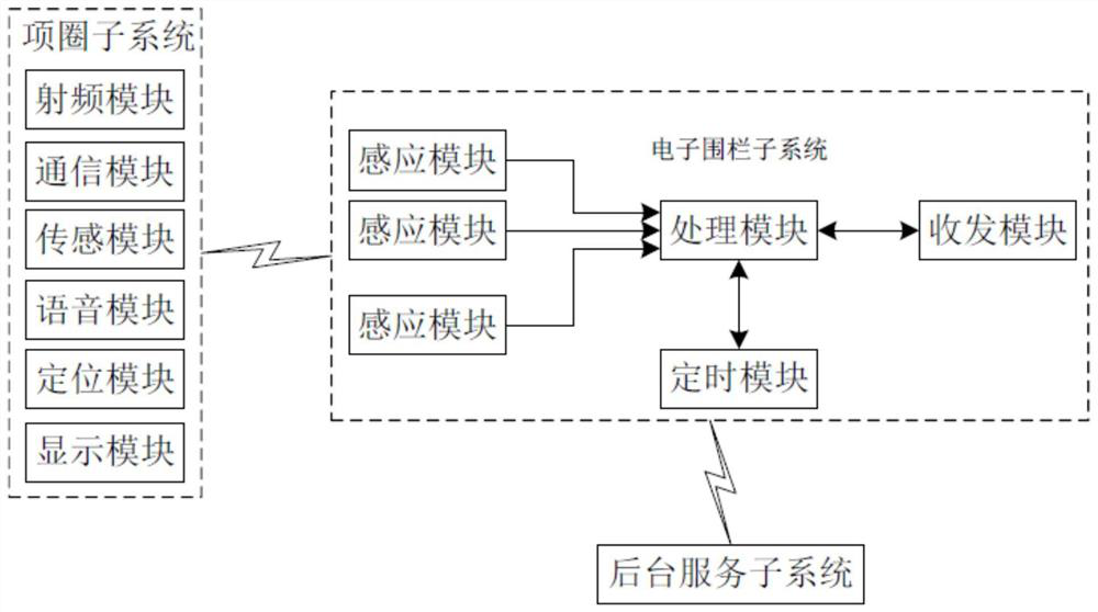
[0032] Pet electronic fence system based on smart city, such as figure 1 Shown: including the collar subsystem, the electronic fence subsystem and the background service subsystem, the collar subsystem includes multiple, the collar subsystem corresponds to the number of pets one by one, the applicable pets are mainly cats and dogs, the collar subsystem includes the radio frequency module And the communication module, the radio frequency module can use the existing RFID tag, the communication module can use the existing 3G mobile communication module, the electronic fence subsystem includes the transceiver module, the processing module and a plurality of sensing modules, the transceiver module can use the existing 3G mobile communication module The radio frequency module sends a sensing signal to the sensing module through the communication module, and the sensing module sends the sensing signal and the preset identification code to the processing module through the transceiver ...
Embodiment 2
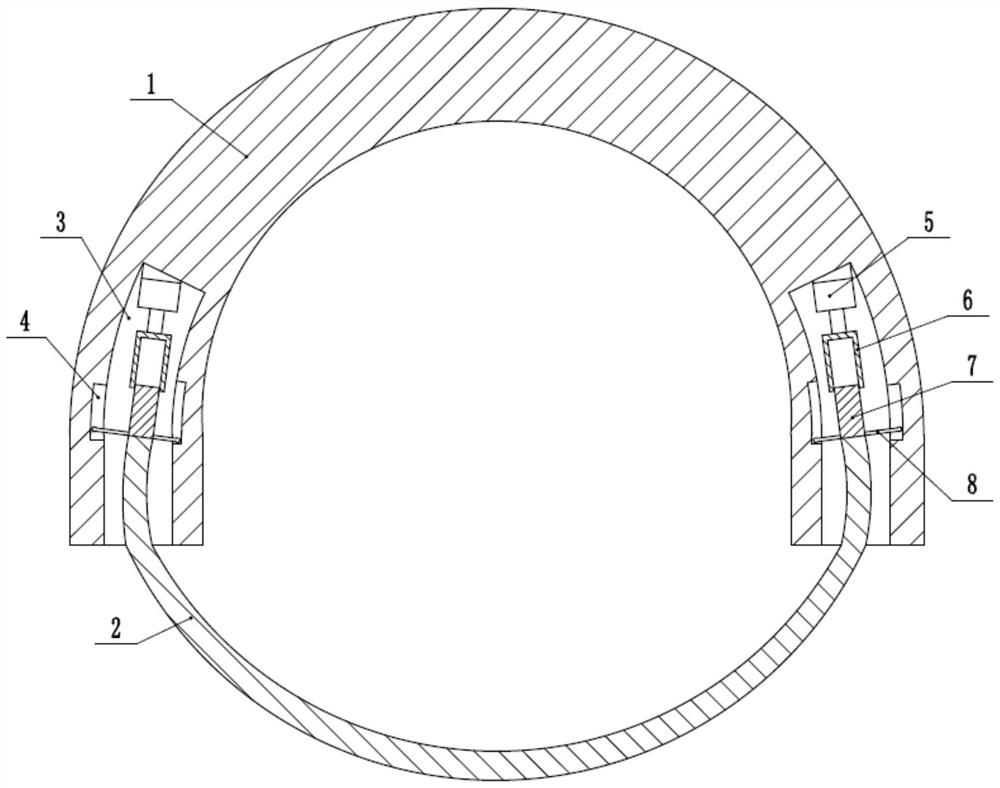
[0043] The difference with Embodiment 1 is that, if figure 2 As shown, the collar subsystem also includes a collar body worn on the neck of the pet. The collar body includes a half-ring section 1 and a moving section 2. Adjustment grooves 3 are respectively opened in the two ends of the half-ring section 1, and the adjustment groove 3 is installed with Adjusting mechanism, the two ends of the moving section 2 are connected to the adjusting mechanism, and the adjusting mechanism drives the moving section 2 to adjust the length. , the motor 5 is bonded in the adjustment groove 3, the adjustment sleeve 6 is welded on the output shaft of the motor 5, the axial section of the adjustment sleeve 6 is concave, the inner wall of the adjustment sleeve 6 has an internal thread, and the adjustment column head 7 has an outer thread. Screw thread, the adjustment column head 7 is threadedly connected in the adjustment sleeve 6, the two ends of the moving section 2 are welded on the end of t...
Embodiment 3
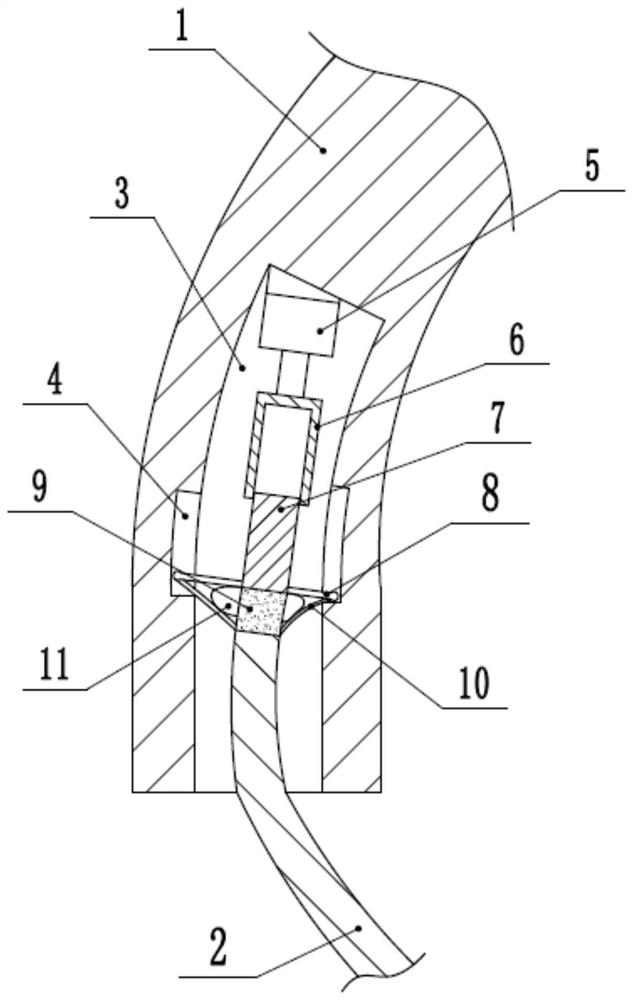
[0046] The difference with Embodiment 2 is that, if image 3 As shown, an elastic section 9 is welded between the adjustment post 7 and the moving section 2, the elastic section 9 can be made of rubber, and the end of the elastic section 9 close to the moving section 2 is bonded with an elastic sheet 10, and the elastic sheet 10 is far away from the elastic section The end of 9 is bonded on the end of adjusting post 7, and the end of adjusting post 7 close to moving section 2 is bonded with self-resetting elastic air bag 11, and the elastic air bag 11 is provided with a ventilation hole. Contact the elastic air bag 11 under the state.
[0047] When the pet wears the collar body initially, the pet may repeatedly flex the collar body due to discomfort, causing the pet to leave the collar body and cannot be monitored. This solution adjusts the elastic section 9 between the column head 7 and the moving section 2 , when the pet moves to the collar body, it can drive the elastic se...
PUM
 Abstract
Description
Claims
Application Information
 - Generate Ideas
- Intellectual Property
- Life Sciences
- Materials
- Tech Scout
- Unparalleled Data Quality
- Higher Quality Content
- 60% Fewer Hallucinations
Browse by: Latest US Patents, China's latest patents, Technical Efficacy Thesaurus, Application Domain, Technology Topic, Popular Technical Reports.
© 2025 PatSnap. All rights reserved.Legal|Privacy policy|Modern Slavery Act Transparency Statement|Sitemap|About US| Contact US: help@patsnap.com


