
Vibration assembly and sound production device

A technology of vibrating components and elastic components, applied in the direction of electrical components, sensors, etc., can solve the problems of complex elastic wave forming process, occupying a large vertical space of the loudspeaker cavity, and occupying a large space

Pending Publication Date: 2021-07-06
GOERTEK INC
View PDF0 Cites 0 Cited by
  • Summary
  • Abstract
  • Description
  • Claims
  • Application Information

AI Technical Summary

Problems solved by technology

[0004] 1. The brocade thread goes out above the elastic wave, which needs to occupy the vertical space in the large speaker cavity, which is not conducive to the thin design of the product; 2. Most of the existing elastic wave materials are fiber or blended materials. This structure and The elastic part of the material not only occupies a large space in the height direction of the sounding device, but also is limited by the material. It is difficult to make the Kms (mechanical stiffness) of the elastic part small. When the vibration displacement of the sounding device is large, the elastic The compliance provided by the part becomes worse, and it is difficult to reduce the F0 of the monomer
3. The existing elastic wave materials are easily affected by environmental changes. For example, they are easily deformed in high temperature and high humidity environments, their hardness changes, and their fatigue resistance is relatively poor.
4. The elastic wave forming process is more complicated

Method used


Image

  • Vibration assembly and sound production device
  • Vibration assembly and sound production device
  • Vibration assembly and sound production device

Examples


Embodiment Construction

[0048] Various exemplary embodiments of the present invention will now be described in detail with reference to the accompanying drawings. It should be noted that the relative arrangements of components and steps, numerical expressions and numerical values ​​set forth in these embodiments do not limit the scope of the present invention unless specifically stated otherwise.

[0049] The following description of at least one exemplary embodiment is merely illustrative in nature and in no way taken as limiting the invention, its application or uses.

[0050] Techniques, methods and devices known to those of ordinary skill in the relevant art may not be discussed in detail, but where appropriate, such techniques, methods and devices should be considered part of the description.

[0051] In all examples shown and discussed herein, any specific values ​​should be construed as exemplary only, and not as limitations. Therefore, other instances of the exemplary embodiment may have diffe...


PUM


Abstract

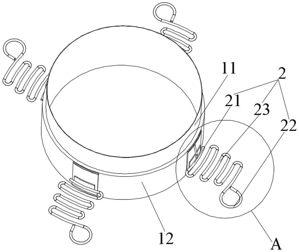
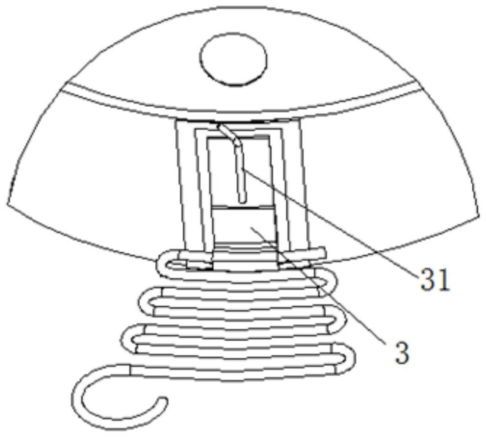
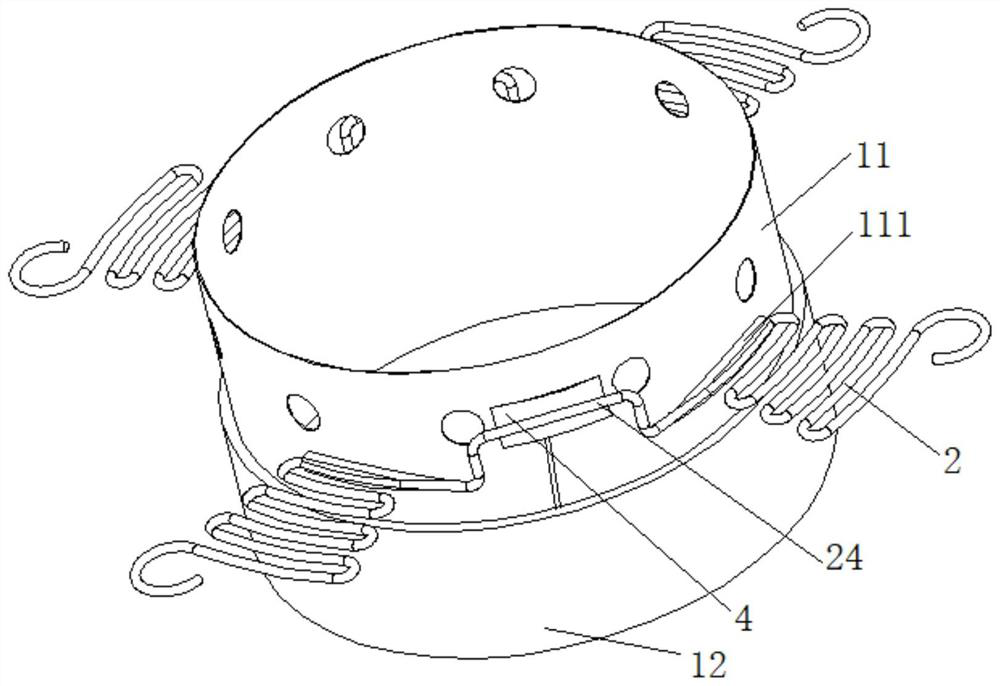
The invention discloses a vibration assembly and a sound production device. The vibration assembly comprises a coil and an elastic part cooperatively connected with the coil, and the coil comprises a skeleton and a coil body wound on the outer side of the skeleton; the coil body is configured to be capable of introducing an electric signal; the elastic part is at least partially formed by a narrow and long electric conductor and comprises a first connecting part and a second connecting part, and the first connecting part is configured to be electrically connected and matched with a wiring part of a coil of the sound production device and is used for transmitting an external electric signal to the coil through the electric conductor on the elastic part; the second connecting part is configured to be fixedly connected in the sound production device and is used for connecting an external circuit; the deformation part is positioned between the first connecting part and the second connecting part and is connected with the first connecting part and the second connecting part, and the body structure of the deformation part is elastically telescopic; the elastic part elastically restrains the coil according to the vibration offset state of the coil, so that the coil is stabilized in a preset central area.

Description

technical field [0001] The invention relates to the technical field of electroacoustic conversion, and more specifically, to a vibrating component and a sound generating device. Background technique [0002] As a traditional electro-acoustic conversion device, the loudspeaker is widely used in consumer electronics, automotive electronics and other fields. With the continuous progress and innovation of technology, the structural design of traditional large speakers is also constantly seeking innovation and change. Taking into account the simplification of the process and the control of the cost. [0003] refer to Figure 24 As shown, in the prior art, the vibration assembly of a large speaker product includes a skeleton 01 and an enameled coil 02 wound on the outside. The enameled coil 02 receives external electrical signals and often depends on two or more wires that are set separately and are made of different materials from the enameled wire. Brocade thread 03 to achieve...

Claims


Application Information

Patent Timeline
IPC IPC(8): H04R9/02H04R9/06H04R31/00
CPCH04R9/02H04R9/06H04R31/00
Inventor 刘春发杨健斌郭晓冬刘光磊
Owner GOERTEK INC
Learn More