Electrical protection device

A technology of electrical protection devices and resistors, applied in emergency protection devices, electrical components, protection switches, etc., can solve the problems that electrical protection devices cannot achieve electrical protection effects well, and achieve the effect of improving electrical protection effects

Pending Publication Date: 2020-02-28
珠海盛世云科智能技术有限公司
View PDF0 Cites 0 Cited by
  • Summary
  • Abstract
  • Description
  • Claims
  • Application Information

AI Technical Summary

Problems solved by technology

[0003] Aiming at the deficiencies of the prior art, the purpose of the present invention is to at least solve one of the technical problems existing in the prior art, and provide an electrical protection device, which is used to solve the problem that the existing electrical protection device cannot achieve the electrical protection effect well. question

Method used


Image

  • Electrical protection device
  • Electrical protection device
  • Electrical protection device

Examples


Embodiment Construction

[0017] The above description is only an overview of the technical solution of the present invention. In order to better understand the technical means of the present invention, it can be implemented according to the contents of the description, and in order to make the above and other purposes, features and advantages of the present invention more obvious and understandable , the following preferred embodiments are specifically cited below, and are described in detail as follows in conjunction with the accompanying drawings.

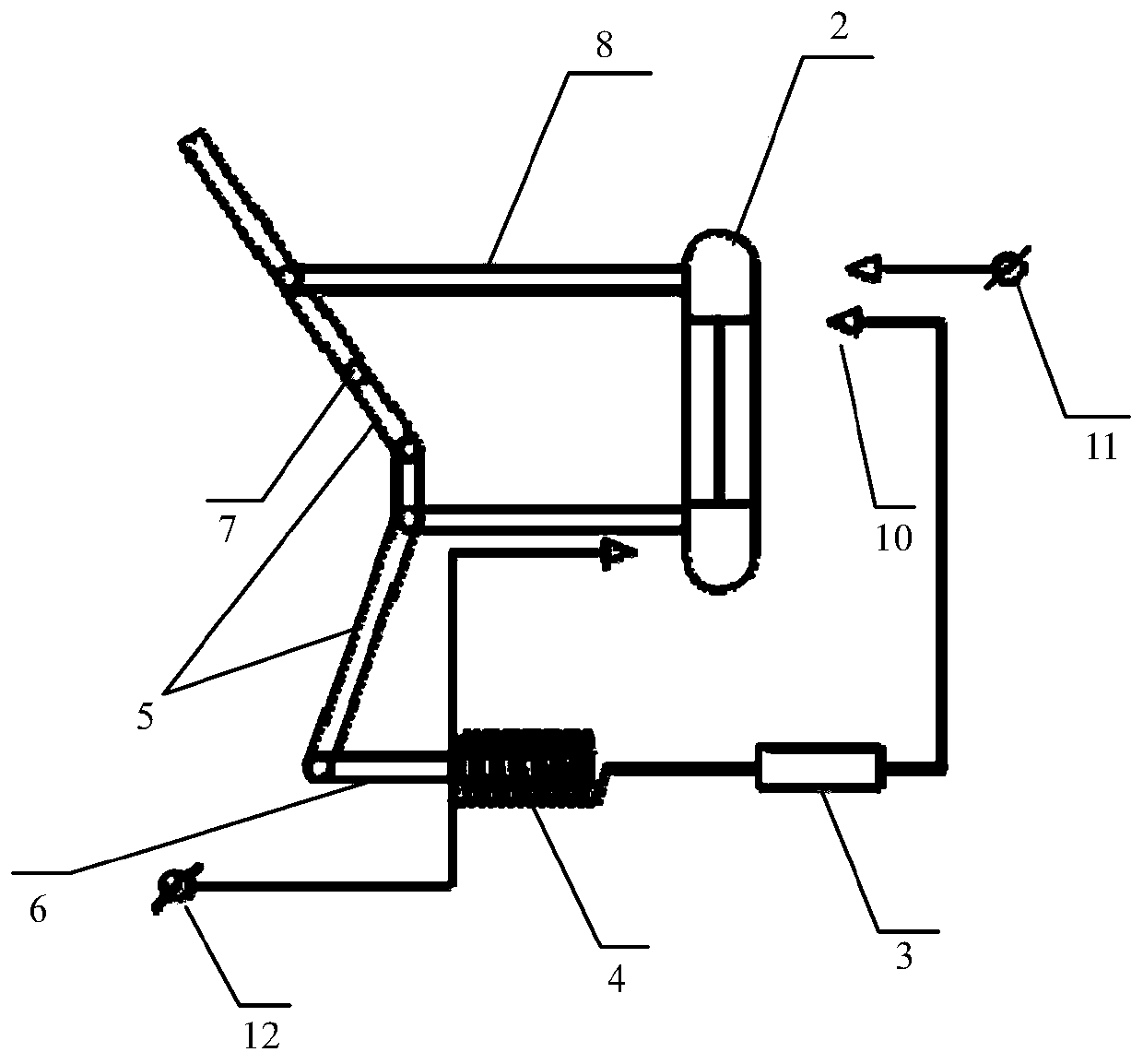
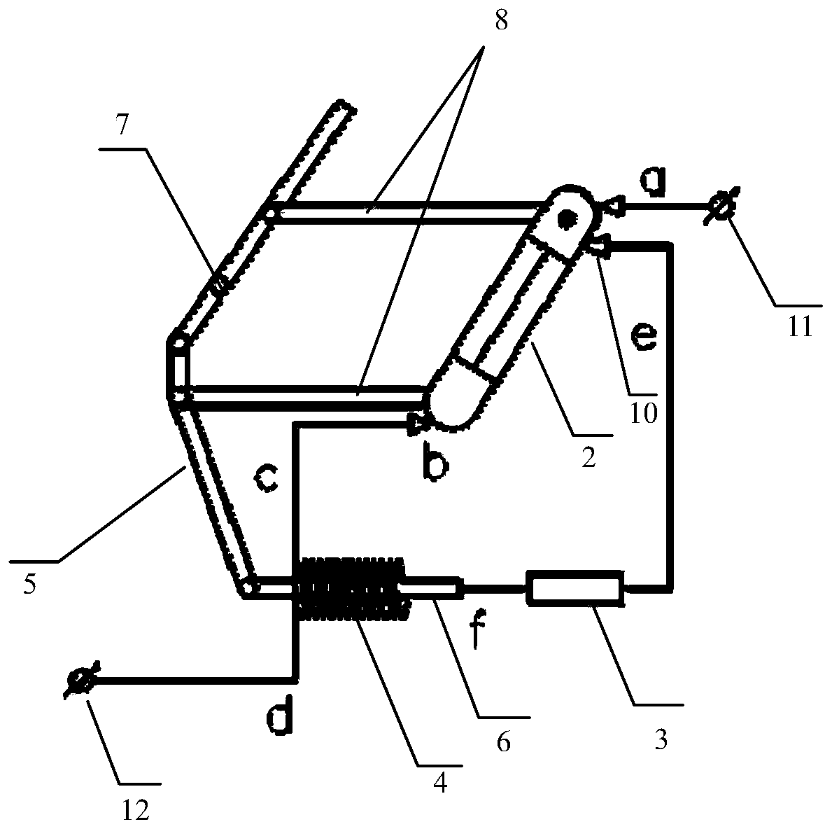
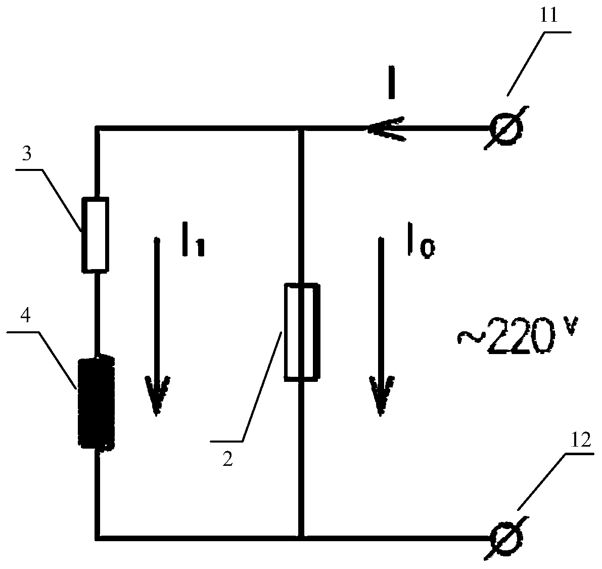
[0018] Please refer to Figure 1-3 , an electrical protection device disclosed in this embodiment includes an insulating case 1 and a fuse tube 2 , a resistor 3 , an electromagnetic coil 4 and a mechanical connecting rod 5 all arranged inside the insulating case 1 , and the insulating case 1 is provided with There are a first terminal 10, an incoming terminal 11 and an outgoing terminal 12, the first terminal after the resistor 3 and the electromagnetic ...


PUM


Abstract

The invention discloses an electrical protection device, which comprises an insulating shell, a fuse tube, a resistor, an electromagnetic coil and a mechanical connecting rod. The insulating shell isprovided with a first wiring terminal, a lead-in terminal and a lead-out terminal. After the resistor and the electromagnetic coil are connected in series, a first end is electrically connected to thefirst wiring terminal, and a second end is electrically connected to the lead-out terminal. The electromagnetic coil is provided therein with a metal rod connected to the mechanical connecting rod. The mechanical connecting rod is connected to the fuse tube and is used for driving the fuse tube to rotate. The first end of the fuse tube can be electrically connected to the lead-in terminal the first wiring terminal, and the second end of the fuse tube can be electrically connected to the lead-out terminal. When the fuse tube is fused due to overcurrent or overvoltage, the current flows throughthe electromagnetic coil and causes the electromagnetic coil to generate a high-intensity magnetic field. The high-intensity magnetic field drives the mechanical connecting rod through a metal rod, thereby disconnecting the fuse tube from the first wiring terminal and the lead-in terminal, realizing the automatic trip-out after the fuse tube is fused, and improving an electrical protection effect.

Description

technical field [0001] The invention relates to the technical field of electrical protection, in particular to an electrical protection device. Background technique [0002] In the power system, in order to improve the safety of electricity use, it is generally necessary to install electrical protection devices. At present, miniature circuit breakers are usually used as electrical protection devices in the low-voltage section of power systems. However, the overcurrent protection current value of miniature circuit breakers is generally greater than 10A. For power systems with operating currents less than 10A, miniature circuit breakers cannot achieve overcurrent protection. Features. In order to realize overcurrent protection with working current less than 10A, some power systems use fuses as electrical protection devices. However, fuses do not have the second-stage protection function of circuit breakers, nor can they achieve good electrical protection effects. Contents o...

Claims


Application Information

Patent Timeline
Patent Type & Authority Applications(China)
IPC IPC(8): H01H71/12H01H71/24H01H9/10
CPCH01H9/10H01H71/122H01H71/24
Inventor 李越
Owner 珠海盛世云科智能技术有限公司
Why Eureka
Try Eureka