Electric power safety power supply device

A power supply device and power safety technology, which is applied to coupling devices, parts of connection devices, circuits, etc., can solve the problems of children easily pulling plugs

Active Publication Date: 2021-07-06
STATE GRID CORP OF CHINA +2
View PDF6 Cites 0 Cited by
  • Summary
  • Abstract
  • Description
  • Claims
  • Application Information

AI Technical Summary

Problems solved by technology

[0004] The technical problem to be solved by the present invention is to provide a safe electric power supply device to solve the problem that children are easy to pull out the plug when the plug is difficult to pull out

Method used


Image

  • Electric power safety power supply device
  • Electric power safety power supply device
  • Electric power safety power supply device

Examples


Embodiment 1

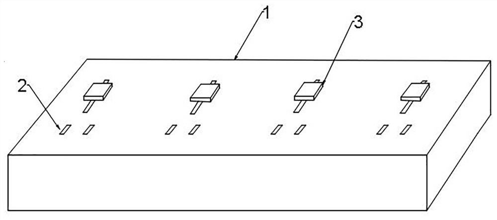
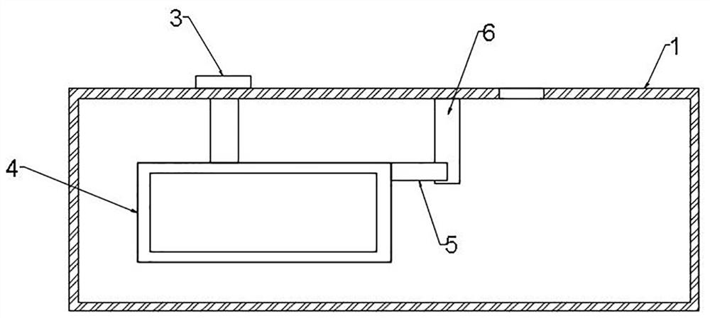
[0045] Such as Figure 1-Figure 3 As shown, an electric safety power supply device includes a socket shell 1, a carrier frame and a plug-in locking mechanism; the socket shell 1 is provided with a jack 2; the socket shell 1 is provided with a through groove, and one end of the through groove faces the jack 2 The carrier includes a push piece 3 and a bearing seat 4; the push piece 3 is fixedly connected to the upper end of the bearing seat 4; the bearing seat 4 is arranged in the socket shell 1, and the push piece 3 is arranged outside the socket shell 1; the push piece 3 is connected to the socket through the slot The socket shell 1 is slidingly connected; the plug-in locking mechanism includes a split piece 5 and a separation column 6, the split piece 5 is two split columns that fit together, and one end of the split piece 5 is fixedly connected to the bearing seat 4; the separation The column 6 is fixedly connected to the inner wall of the socket housing 1 , and the separati...

Embodiment 2

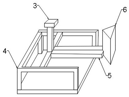
[0051] Such as Figure 4-Figure 8 As shown, this embodiment relates to an electric power supply device, which has roughly the same structure as that of Embodiment 1. This embodiment is further optimized on the basis of Embodiment 1: the separation column 6 is a triangular prism, and the top surface of the separation column 6 It is fixedly connected to the inner wall of the socket housing 1 , and the two side surfaces of the separation column 6 abut against the free ends of the two split pieces 5 respectively.

[0052] The separation column 6 is a prism, which can control the width of the split sheet 5 when separated by the angle formed by the slopes on both sides, and the setting of the prism can facilitate the split sheet 5 to slide over on both sides of the prism, reducing the friction between the split sheet 5 and the prism force.

[0053] In order to further optimize the electric safety power supply device of the present invention, the lower end of the socket 2 is provide...


PUM


Abstract

The invention discloses an electric power safety power supply device which comprises a socket shell, a bearing frame and an insertion piece clamping mechanism. The socket shell is provided with a through groove allowing the bearing frame to move, the bearing frame comprises a push piece and a bearing seat, the bearing seat is fixedly connected with an insertion piece clamping mechanism, the insertion piece clamping mechanism comprises split pieces and a separation column arranged between the split pieces, the split pieces are split columns which are attached to each other, and the separation column is fixedly connected to the inner wall of the socket shell. One end of each split piece is fixedly connected with the bearing seat, the other end faces the jacks, and the width of each split piece is smaller than the distance between the jacks. According to the invention, the bearing seat drives the conductive sheet and the split sheet to move towards the lower part of the jack, the width of the split sheet is continuously increased in the moving process of the split sheet, the split sheet gradually abuts against the insertion sheet so that the insertion sheet cannot be pulled out, the split sheet can only loosen abutting against the insertion sheet by moving the bearing seat, and the separation of the bearing seat enables the insertion sheet to lose electric connection. The problem that when the plug is not easy to pull out, children are easy to pick the plug is solved.

Description

technical field [0001] The invention belongs to the field of electric safety equipment, in particular to an electric safety power supply device. Background technique [0002] Socket (claim again supply socket, combined socket and switch) refers to the insertable seat of one or more circuit connections, can insert various wiring by it, is convenient to connect with other circuits. The power socket is an electrical device that provides a power interface for household appliances, and it is also an electrical accessory that is used more in residential electrical design. It has a very close relationship with people's lives. After residents moved into their new residences, they generally reported that the number of power sockets was too small, which was extremely inconvenient to use, causing residents to connect power cords indiscriminately and install socket wiring boards, which often caused personal electric shocks and electrical fire accidents, which brought great harm to perso...

Claims


Application Information

Patent Timeline
Patent Type & Authority Applications(China)
IPC IPC(8): H01R13/447H01R13/629H01R13/52
CPCH01R13/447H01R13/629H01R13/52
Inventor 张桂霞范玮璟王岩
Owner STATE GRID CORP OF CHINA
Why Eureka
Try Eureka