Y-shaped tunnel grouting structure and matched grouting method

A technology of grouting and tunneling, which is applied in tunnels, tunnel linings, earthwork drilling and mining, etc., and can solve problems such as unsolvable segment floating phenomenon, segment floating, cumbersome construction process, etc.

Active Publication Date: 2021-07-06
JILIN UNIV +2
View PDF9 Cites 1 Cited by
  • Summary
  • Abstract
  • Description
  • Claims
  • Application Information

AI Technical Summary

Problems solved by technology

[0003] During shield construction, there are often gaps between the pipe layer and the rock-soil layer. In order to prevent surface subsidence, it is necessary to inject grout between the pipe layer and the rock-soil layer. In actual engineering, researchers have found that synchronous grouting cannot Effectively fills the gap at the back of the segment, but the grouting effect is poor, and the tunnel segment cannot be fixed in time, and the segment is prone to float up and damage the tunnel structure
[0004] The existing tunnel secondary grouting structure and method settings are not reasonable enough
Setting vertical grouting holes at 11 o'clock and 1 o'clock on the top of the segment for secondary grouting will result in gaps on the back of the segment and poor grouting effect; top grouting solves the problem of gaps on the back of the segment to a certain extent Problem, but during the grouting process, the grout gradually rises from the bottom to the top, so the buoyancy of the grout on the segment rises to a certain level before the upper half of the tunnel begins to have grout, so this grouting method cannot solve the phenomenon of the segment floating up ; Although the circumferential grouting method can restrain the segment from floating to a certain extent, its grouting efficiency is low and the construction process is cumbersome

Method used


Image

  • Y-shaped tunnel grouting structure and matched grouting method
  • Y-shaped tunnel grouting structure and matched grouting method
  • Y-shaped tunnel grouting structure and matched grouting method

Examples


Embodiment 1

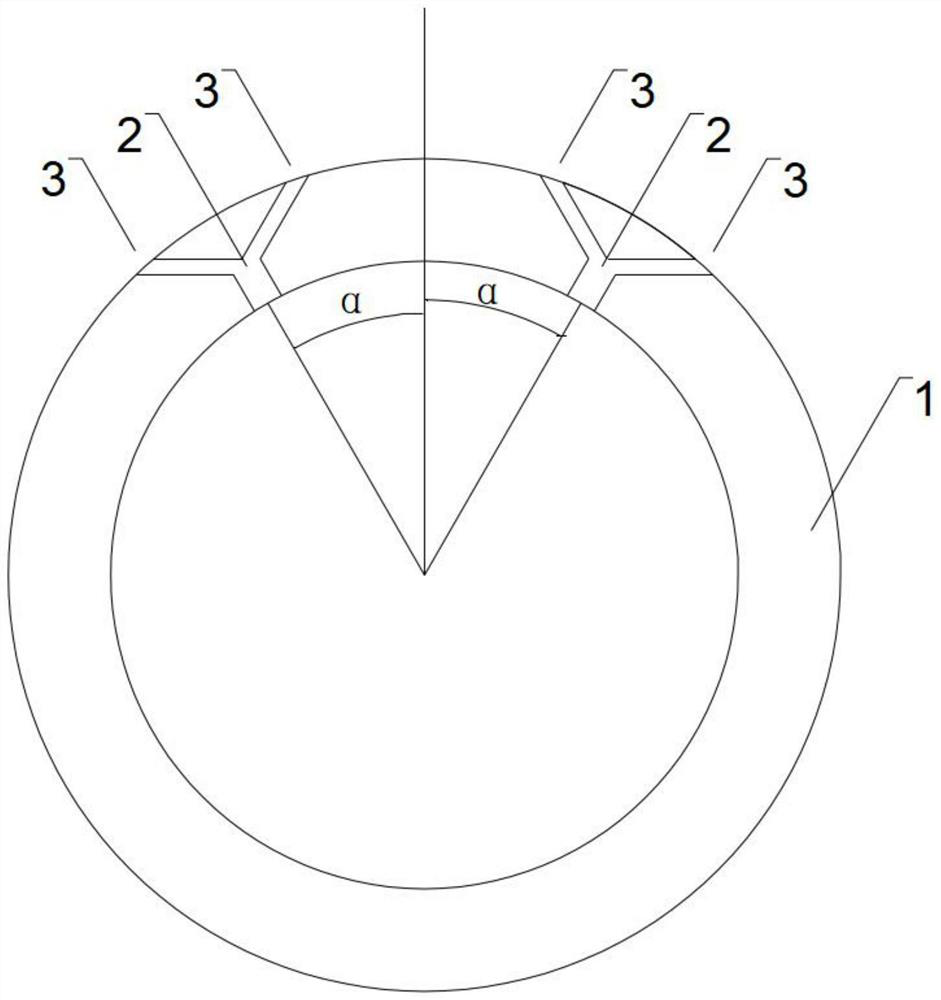
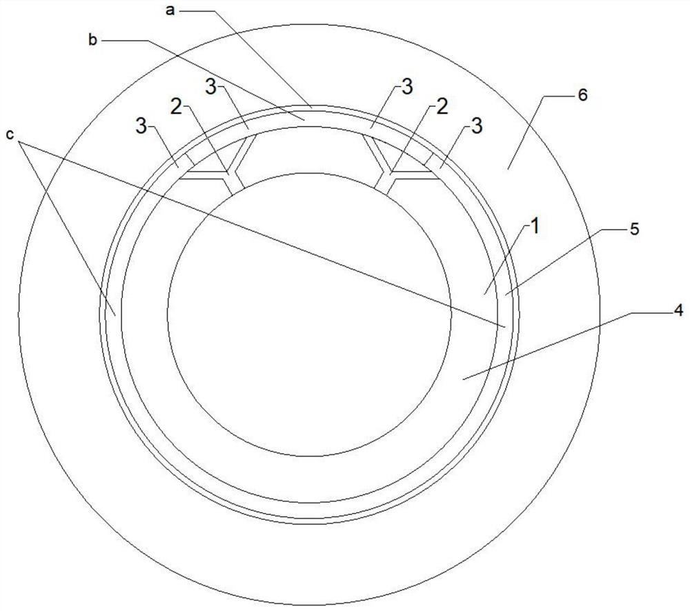
[0034] Embodiment 1: A kind of grouting structure in tunnel excavation process, please refer to figure 1 and figure 2 , the embodiment of the present invention includes:

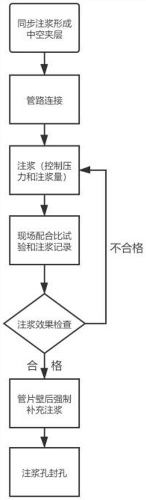
[0035] From the tunnel rock layer 6, it includes the rock layer 6, the grouting layer and the pipe layer 4 in sequence. The pipe layer 4 is provided with a grouting hole, and the grouting hole is grouted outward. The surface of the rock layer 6 is formed by synchronous grouting. A hard shell, forming a grouting layer between the hard shell and the segment layer 4; a pair of Y-shaped pre-grouting holes 2, Y The reserved hole 2 for grouting has two pipes for spraying slurry upward and downward; the reserved hole 2 for Y-shaped grouting sprays liquid A upward, and the reserved hole 2 for Y-shaped grouting sprays liquid B downward; Type grouting reserved hole 2 is movably connected to a grouting pipeline, and the other end of the pipeline is connected to a grouting machine injecting liquid A and liquid B resp...

Embodiment 2

[0057] Embodiment 2: A kind of grouting structure in the tunnel excavation process, please refer to figure 1 and figure 2 , the embodiment of the present invention includes:

[0058] From the tunnel rock layer 6, it includes the rock layer 6, the grouting layer and the pipe layer 4 in sequence. The pipe layer 4 is provided with a grouting hole, and the grouting hole is grouted outward. The surface of the rock layer 6 is formed by synchronous grouting. A hard shell, forming a grouting layer between the hard shell and the segment layer 4; a pair of Y-shaped grouting reserved holes 2, Y The reserved hole 2 for grouting has two pipes for spraying slurry upward and downward; the reserved hole 2 for Y-shaped grouting sprays liquid A upward, and the reserved hole 2 for Y-shaped grouting sprays liquid B downward; Type grouting reserved hole 2 is movably connected to a grouting pipeline, and the other end of the pipeline is connected to a grouting machine injecting liquid A and liqu...

Embodiment 3

[0072] Embodiment 3: A kind of grouting structure in the process of tunnel excavation, please refer to figure 1 and figure 2 , the embodiment of the present invention includes:

[0073] From the tunnel rock layer 6, it includes the rock layer 6, the grouting layer and the pipe layer 4 in sequence. The pipe layer 4 is provided with a grouting hole, and the grouting hole is grouted outward. The surface of the rock layer 6 is formed by synchronous grouting. A hard shell, forming a grouting layer between the hard shell and the segment layer 4; a pair of Y-shaped pre-grouting holes 2, Y The reserved hole 2 for grouting has two pipes for spraying slurry upward and downward; the reserved hole 2 for Y-shaped grouting sprays liquid A upward, and the reserved hole 2 for Y-shaped grouting sprays liquid B downward; Type grouting reserved hole 2 is movably connected to a grouting pipeline, and the other end of the pipeline is connected to a grouting machine injecting liquid A and liquid...


PUM


Abstract

The invention belongs to the technical field of tunnel tunneling, and particularly relates to a Y-shaped tunnel grouting structure and a matched grouting method. The Y-shaped tunnel grouting structure sequentially comprises a rock stratum, a grouting layer and a duct piece layer from a tunnel rock stratum to the inside, wherein grouting holes are formed in the duct piece layer, and the grouting holes are used for grouting outwards. The Y-shaped tunnel grouting structure is reasonable in structural design, two kinds of grout are sprayed out through the Y-shaped grouting holes, the two kinds of grout are well suitable for the top, the side part and the bottom of a tunnel respectively, the grouting effect is good, and the efficiency is high; and the two kinds of grout are sprayed upwards and downwards through the Y-shaped grouting holes respectively, the grout sprayed upwards is the grout mixed by mortar and water glass, the characteristics of high viscosity and short setting time are achieved, the back of a duct piece can be effectively filled, the strength can be rapidly generated, the fixing effect on the duct piece structure is achieved, the duct piece is effectively prevented from floating upwards, the grouting can be carried out by depending on existing equipment, the grouting cost is not increased, the utilization rate of the grout is high, two grouting machines work at the same time, the grouting time is short, the grouting pressure can be monitored in real time, and the grouting quality is guaranteed.

Description

technical field [0001] The invention relates to the technical field of tunnel excavation, in particular to a Y-shaped tunnel grouting structure and a matching grouting method. Background technique [0002] The shield tunneling method is often used in the excavation process of subway tunnels. It has the advantages of fast construction speed, no influence of seasons, and no impact on traffic. [0003] During shield construction, there are often gaps between the pipe layer and the rock-soil layer. In order to prevent surface subsidence, it is necessary to inject grout between the pipe layer and the rock-soil layer. In actual engineering, researchers have found that synchronous grouting cannot It effectively fills the gap at the back of the segment, but the grouting effect is poor, and the tunnel segment cannot be fixed in time, and the segment is prone to float up and damage the tunnel structure. [0004] The existing tunnel secondary grouting structure and method setting are ...

Claims


Application Information

Patent Timeline
Patent Type & Authority Applications(China)
IPC IPC(8): E21D11/10E21D11/00E21D11/08C04B28/26C04B28/00C04B111/70
CPCE21D11/105E21D11/006E21D11/08C04B28/26C04B28/00C04B2111/70C04B7/00C04B18/08C04B14/361C04B14/06
Inventor 魏海斌蒋博宇何小送刘佳佳王峰陈东丰蔡贺马建领陈成牟洋
Owner JILIN UNIV
Why Eureka
Try Eureka