Surface point vibration type vibrating rod

A technology of vibrating rods and surface points, which is applied in the fields of construction, building structure, and building materials, and can solve problems such as manual cleaning and removal, affecting construction efficiency, and easy adhesion

Active Publication Date: 2021-07-06
泸州发展华西绿色建材有限公司
View PDF5 Cites 1 Cited by
  • Summary
  • Abstract
  • Description
  • Claims
  • Application Information

AI Technical Summary

Problems solved by technology

[0003] Although the vibrating rod can effectively eliminate most of the voids and air bubbles in the concrete, in actual operation, there will still be some small voids in the concrete slurry, which still have a certain impact on the strength of the formed concrete block, especially It is the concrete slurry near the vibrating end of the vibrating rod. The large vibration effect here will cause part of the outside air to be introduced into this place, and part of the air will not overflow with the vibrating rod when it is taken out, resulting in a certain small gap. In addition, the surface of the vibrating rod is easy to adhere to a certain amount of concrete slurry, which causes the construction personnel to manually clean and remove it, which affects the construction efficiency

Method used


Image

  • Surface point vibration type vibrating rod
  • Surface point vibration type vibrating rod
  • Surface point vibration type vibrating rod

Examples


Embodiment 1

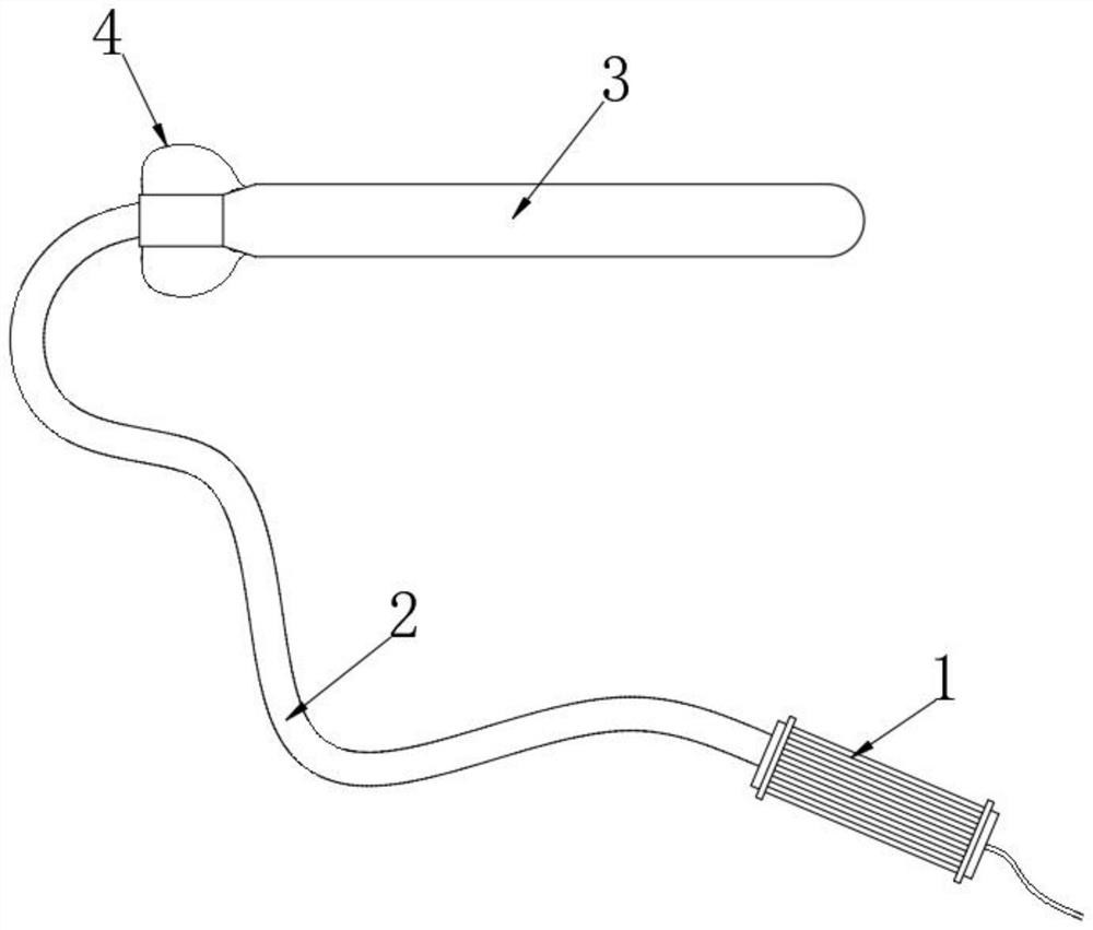
[0043] see figure 1 , a surface point vibration vibrator, including a driver 1, a vibrating end 3 and a hose 2 connected between the driver 1 and the vibrating end 3, and the outer end of the connection between the vibrating end 3 and the hose 2 is fixedly connected There is a drum pressure ring 4. The drum pressure ring 4 is made of elastic sealing material, and the drum pressure ring 4 is filled with compressed gas. The compressed gas is a compressed non-toxic gas, preferably air, and the compression ratio of the air is not more than 1.2 times. If the compression ratio is too large, it is easy to cause the air shock ball 71 to break away from the mouth of the main gas-gathering hole 62 when the pressure drum ring 4 is not pressed, so that when the pressure drum ring 4 is pressed, the internal compressed gas passes through the main gas-gathering hole 62 The rear part directly enters into the ball-shaped groove 61, resulting in a small driving force on the air shock ball 71, s...

Embodiment 2

[0048] see Figure 7 , the air shock cavity includes a gas-gathering auxiliary hole 81 communicating with the U-shaped gas-dispersing chamber 5 and a hemispherical striking groove 82 communicating with the gas-gathering auxiliary hole 81, and the hemispherical striking groove 82 is excavated near the inner bottom of the mouth of the gas-gathering auxiliary hole 81 There is a spherical groove, and the spherical groove matches the air-shock ball 71, so that the air-shock ball 71 can smoothly return to the spherical groove after hitting the outer micro-shock hard shell 32, so that it just blocks the gas-gathering auxiliary hole 81 The mouth part effectively ensures that the air shock hitting ball 71 can receive a relatively large impact force from the inert gas, effectively guarantees the impact force of the external micro-shock hard shell 32, and makes the multi-point micro-vibration effect on the surface of the external micro-shock hard shell 32 Better yet, the cross section of...


PUM


Abstract

The invention discloses a surface point vibration type vibrating rod, and belongs to the field of vibrating rods. According to the surface point vibration type vibrating rod, an outer micro-vibration hard shell is arranged and matched with the action of an air-blowing compression ring, the air-blowing compression ring is pinched during vibrating, compressed air in the air-blowing compression ring is dispersed into an air vibration cavity through a U-shaped air dispersion cavity, an air vibration rebounding ball is driven to impact the outer micro-vibration hard shell, so that the multi-point micro-vibration phenomenon occurs on the surface of the outer micro-vibration hard shell, on one hand, micro-vibration of concrete slurry near the vibrating rod is effectively accelerated, outward overflow of air near the vibrating end is accelerated, therefore small gaps near the vibrating rod are effectively eliminated, the concrete density after vibrating is higher, and the vibrating effect is better; and on the other hand, adhesion of concrete slurry on the surface of the concrete is effectively reduced, meanwhile, after vibration is finished, part of the adhered concrete slurry can fall off through vibration, and the influence of manual cleaning on the construction efficiency is effectively avoided.

Description

technical field [0001] The invention relates to the field of vibrating rods, more specifically, to a surface point vibration type vibrating rod. Background technique [0002] The vibrating rod is also called the vibrating rod, which is composed of cables (with leakage protector), driver, (220V) rubber tube, vibrating rod (built-in motor) and other components. Using low-voltage (safety voltage 42V) high-frequency (200Hz) power supply, a micro-motor is directly built into the plug-in vibrating rod to drive the eccentric block, and the vibration frequency is as high as 12,000 times per minute, which is very easy to resonate with the concrete component and cause air bubbles in the component Quickly discharged, the cement, sand and steel frame are closely integrated to achieve the compactness of the concrete and high surface finish. [0003] Although the vibrating rod can effectively eliminate most of the voids and air bubbles in the concrete, in actual operation, there will sti...

Claims


Application Information

Patent Timeline
IPC IPC(8): E04G21/08
CPCE04G21/08
Inventor 丘永梅
Owner 泸州发展华西绿色建材有限公司
Why Eureka
Try Eureka