
Long and narrow underground structure suitable for strong earthquake action and construction method thereof

A technology for underground structures and construction methods, which is applied in the field of seismic resistance of underground structures, and can solve problems such as prone to damage, difficult to popularize and apply, and differential settlement damage of stations

Active Publication Date: 2021-07-06
SHANGHAI URBAN CONSTR DESIGN RES INST GRP CO LTD
View PDF7 Cites 1 Cited by
  • Summary
  • Abstract
  • Description
  • Claims
  • Application Information

AI Technical Summary

Problems solved by technology

However, this does not solve the seismic problem of the main structure. When the main structure is severely damaged in the face of a strong earthquake, the above-mentioned internal components will inevitably be destroyed.
The second is to wrap a thick shock-isolation layer composed of foam resin and other buffering and damping media around the periphery of the underground structure, but the corresponding construction cost is high, and the above-mentioned materials are prone to creep compression under long-term continuous loads, and the structural bottom plate The compression deformation of the seismic isolation layer below and above the roof will cause differential settlement damage of the station, cracking damage of the ground road, etc., so it is difficult to popularize and apply
However, this method not only significantly increases the engineering investment, but also, engineering practice shows that blindly increasing the structural stiffness without considering enough energy-dissipating components is more likely to damage

Method used


Image

  • Long and narrow underground structure suitable for strong earthquake action and construction method thereof
  • Long and narrow underground structure suitable for strong earthquake action and construction method thereof

Examples


Embodiment

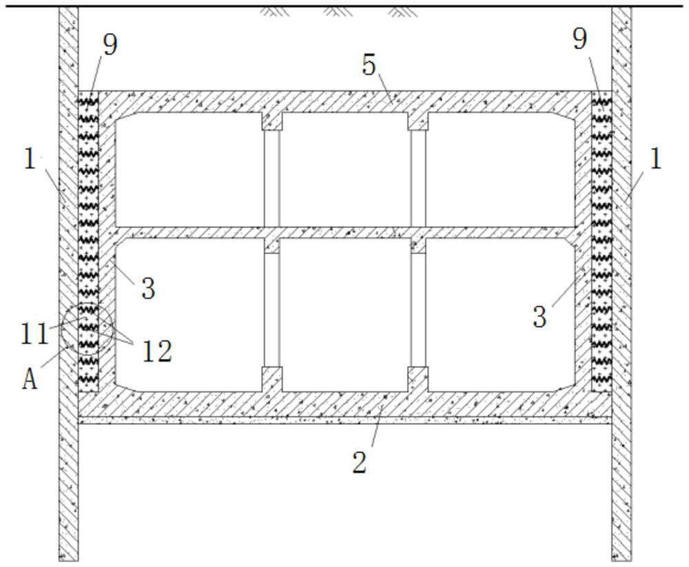
[0035] Such as figure 1 and figure 2 As shown, a long and narrow underground structure adapted to strong earthquake action, a matrix energy-dissipating layer 9 is set between the side wall 3 of the underground structure and the enclosure structure 1 .

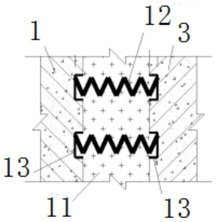
[0036] Wherein, the matrix energy dissipation layer 9 includes a plurality of steel springs 12;

[0037] A plurality of steel springs 12 are arranged in an array, and the spaces between the plurality of steel springs 12 are filled with cement soil 11 .

[0038] In some embodiments, a spring embedded part 13 is provided corresponding to each steel spring 12 on the side wall 3 and the enclosure structure 1;

[0039] Each spring embedded part 13 is used to fix the corresponding steel spring 12 .

[0040] In some embodiments, the embedding depth of each spring embedded part 13 is 100mm;

[0041] The spacing between every two horizontally or vertically adjacent spring embedded parts 13 is 700mm;

[0042] The space reserved for...


PUM


Abstract

The invention discloses a long and narrow underground structure suitable for strong earthquake action and a construction method thereof. A matrix energy consumption layer is arranged between side walls of the underground structure and an enclosure structure; the matrix energy consumption layer comprises a plurality of steel springs; the plurality of steel springs are arranged in an array mode, and the plurality of steel springs are filled with cement soil; during construction, firstly, the enclosure structure is constructed, and spring embedded parts are arranged on the enclosure structure; secondly, and during side wall construction, corresponding spring embedded parts are arranged on the soil facing sides of the side walls; after the side walls reach the design strength, the steel springs are mounted one by one; thirdly, cement soil is filled between the side walls and the enclosure structure to the top surface of a top plate of the underground structure; and finally, the top plate is covered with soil and backfilled to the designed ground elevation. The application of the method can obviously improve the adaptive capacity of the long and narrow underground structure under the strong earthquake action, and has the characteristics of convenience in construction and low manufacturing cost.

Description

technical field [0001] The invention relates to the technical field of seismic resistance of underground structures, in particular to a long and narrow underground structure adaptable to strong earthquakes and a construction method thereof. Background technique [0002] For a long time, it has been generally believed that long and narrow underground structures completely buried in the soil, such as subway stations, urban underground road tunnels, and underground comprehensive pipe corridors, are subject to earthquakes due to the constraints of the foundation soil and the simple and regular structural system. less harmful. However, the existing earthquake damage shows that this type of structure is not safe when a strong earthquake disaster occurs. For example, the Great Hanshin Earthquake in Japan in 1995 caused the most serious damage in history to the subways, underground businesses, and tunnels in Kobe City. [0003] In the existing technology, some explorations have be...

Claims


Application Information

Patent Timeline
Patent Type & Authority Applications(China)
IPC IPC(8): E02D29/045E02D31/08E02D29/00
CPCE02D29/045E02D31/08E02D29/04E02D29/10
Inventor 张中杰吕培林陈加核郑雅莉刘书
Owner SHANGHAI URBAN CONSTR DESIGN RES INST GRP CO LTD
Learn More