
Pneumatic recoil type stamping die and using method thereof

A stamping die and recoil technology, applied in the field of pneumatic recoil stamping die, can solve the problems of product demoulding damage, affecting processing efficiency, and product quality decline.

Inactive Publication Date: 2021-07-06
刘倩
View PDF4 Cites 0 Cited by
  • Summary
  • Abstract
  • Description
  • Claims
  • Application Information

AI Technical Summary

Problems solved by technology

[0003] The clamping mold consists of an upper mold, a lower mold, a mold cavity and a mold core. This type of mold injects slurry water after the mold is closed. The slurry water is formed in the mold cavity and can be demoulded after a certain period of cooling. However, during this process, cooling The slurry needs to be completely injected into the chamber, otherwise, there will be differences in the integrity of the internal injection molding product, resulting in a decrease in product quality, which will increase the molding time, and the cooled product needs to be manually demoulded. Manual participation not only affects the processing efficiency, It will also cause damage when the product is demolded

Method used


Image

  • Pneumatic recoil type stamping die and using method thereof
  • Pneumatic recoil type stamping die and using method thereof
  • Pneumatic recoil type stamping die and using method thereof

Examples


Embodiment Construction

[0028] The embodiments of the present application will be described in detail below with reference to the accompanying drawings and examples, so as to fully understand and implement the implementation process of how to apply technical means to solve technical problems and achieve technical effects in the present application.

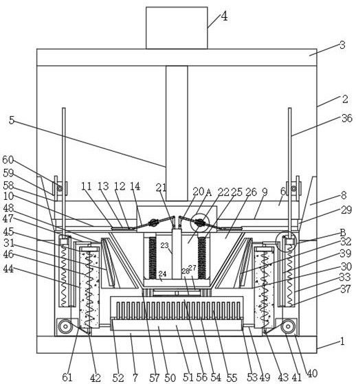
[0029] like Figure 1-4 As shown, the present invention provides a pneumatic recoil stamping die, comprising: a base 1, the top of the base 1 is fixedly connected with a fixed table 3 through a support plate 2, and a hydraulic telescopic cylinder 4 is fixedly connected to the top of the fixed table 3, and the hydraulic telescopic The free end of the cylinder 4 is fixedly connected with a connecting rod 5, the bottom end of the connecting rod 5 penetrates the fixing table 3 and extends below it, the top of the base 1 is fixedly connected with a lower die sleeve 7, and the bottom end of the connecting rod 5 is fixedly connected with a lower mold sleeve 7. ...


PUM


Abstract

The invention relates to the technical field of dies, in particular to a pneumatic recoil type stamping die. The pneumatic recoil type stamping die comprises a base, wherein the top of the base is fixedly connected with a fixing table through a supporting plate, the top of the fixing table is fixedly connected with a hydraulic telescopic air cylinder, the free end of the hydraulic telescopic air cylinder is fixedly connected with a connecting rod, the bottom end of the connecting rod penetrates through the fixing table and extends to the position below the fixing table, the top of the base is fixedly connected with a lower die sleeve, and the bottom end of the connecting rod is fixedly connected with a lower die sleeve. According to the pneumatic recoil type stamping die, by arranging an air pressure cavity, after injection molding is completed, air in the air pressure cavity is injected into a hydraulic cavity and an annular air bag, in this way, heat exchange liquid and cooling oil can be made to be close to a molded product, the product can be rapidly cooled, the molding time is shortened, the molding efficiency is improved, after molding is completed, in the separation process of an upper die sleeve and the lower die sleeve, air pressure can cool and shape a product, the product can be ejected out of the die cavity through air pressure recoil force after shaping, the whole process is high in continuity, and no manual intervention is needed.

Description

technical field [0001] The invention relates to the technical field of dies, in particular to a pneumatic recoil stamping die and its usage method. Background technique [0002] Molds are various molds and tools used in industrial production for injection molding, blow molding, extrusion, die-casting or forging forming, smelting, stamping and other methods to obtain the required products. In short, a mold is a tool used to make shaped objects. This tool is composed of various parts, and different molds are composed of different parts. It mainly realizes the processing of the shape of the article through the change of the physical state of the formed material. Known as the "Mother of Industry". [0003] The clamping mold consists of an upper mold, a lower mold, a mold cavity and a mold core. This type of mold injects slurry water after the mold is closed. The slurry water is formed in the mold cavity and can be demoulded after a certain period of cooling. However, during th...

Claims


Application Information

Patent Timeline
IPC IPC(8): B29C45/26B29C45/73B29C45/68B29C45/40
CPCB29C45/2602B29C45/2606B29C45/7331B29C45/68B29C45/4005
Inventor 刘倩
Owner 刘倩
Learn More