
Clamping mechanism

A clamping mechanism and clamping technology, applied in the field of robots, can solve the problem that the clamping mechanism is difficult to realize the clamping object and so on.

Active Publication Date: 2021-07-06
BEIJING GUODIAN FUTONG SCI & TECH DEV
View PDF6 Cites 0 Cited by
  • Summary
  • Abstract
  • Description
  • Claims
  • Application Information

AI Technical Summary

Problems solved by technology

[0005] Therefore, the technical problem to be solved by the present invention is to overcome the defect that it is difficult for the clamping mechanism in the prior art to realize that the clamped object can slide freely and be clamped within the locking range of the clamping mechanism.

Method used


Image

  • Clamping mechanism
  • Clamping mechanism
  • Clamping mechanism

Examples


Embodiment Construction

[0045] The technical solutions of the present invention will be clearly and completely described below in conjunction with the accompanying drawings. Apparently, the described embodiments are some of the embodiments of the present invention, but not all of them. Based on the embodiments of the present invention, all other embodiments obtained by persons of ordinary skill in the art without making creative efforts belong to the protection scope of the present invention.

[0046] In the description of the present invention, it should be noted that the terms "center", "upper", "lower", "left", "right", "vertical", "horizontal", "inner", "outer" etc. The indicated orientation or positional relationship is based on the orientation or positional relationship shown in the drawings, and is only for the convenience of describing the present invention and simplifying the description, rather than indicating or implying that the referred device or element must have a specific orientation, ...


PUM


Abstract

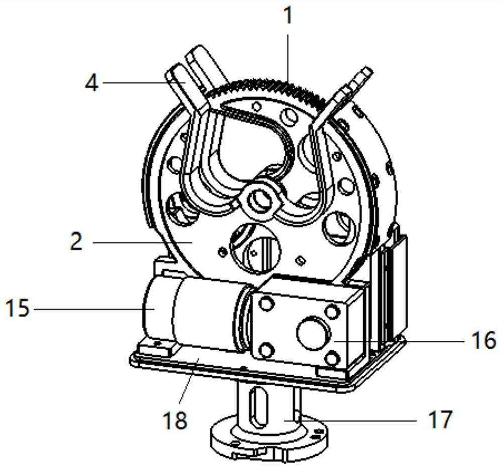
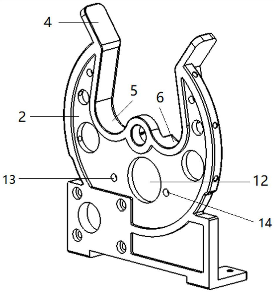
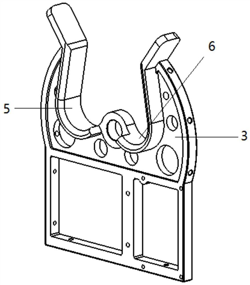
The invention relates to the technical field of robots, and provides a clamping mechanism. The clamping mechanism comprises a clamping seat and a rotating wheel, and a first clamping groove and a second clamping groove of which notches are communicated with each other are formed in the clamping seat; the rotating wheel is rotationally connected to the clamping seat around an axis, and a first clamping groove and a second clamping groove of which notches are communicated are formed in the rotating wheel; and in the rotating process of the rotating wheel, the rotating wheel has a first clamping state that the first clamping groove and the first clamping groove are matched to form a clamping space used for clamping a clamped object, and a second clamping state that the second clamping groove and the second clamping groove are matched to form a locking space used for limiting the clamped object to freely slide in the axial direction of the rotating wheel. The clamping mechanism not only can be used for clamping the clamped object, but also can switch the clamping state, so that the clamped object can freely slide in the axial direction of the clamped object and cannot fall off from the locking space; and moreover, in the switching process of the rotating wheel between the first clamping state and the second clamping state, switching can be completed without taking out the clamped object, and use is more convenient.

Description

technical field [0001] The invention relates to the technical field of robots, in particular to a clamping mechanism. Background technique [0002] Smart grid live work is the future development trend, live work robot is a kind of live work intelligent equipment that can replace manual operation. The mechanical clamping mechanism is an indispensable mechanical device when the live robot works. At present, there are many types of clamping mechanisms at the end of the live robot on the market, mainly double splint type and bionic gripper. [0003] The advantage of the double splint mechanism is that the mechanism is simple, easy to design, and small in weight; the disadvantage is that the holding capacity is poor, and the function is single, and usually only small-scale objects can be clamped. Bionic grippers are mainly used to grip irregular and prominent objects, such as industrial parts or household appliances, and the multi-claw mechanism has the disadvantages of heavy we...

Claims


Application Information

Patent Timeline
Patent Type & Authority Applications(China)
IPC IPC(8): B25J15/00
CPCB25J15/00
Inventor 徐善军郭俊龙孙霄伟张铜鞠忆南王勇琦
Owner BEIJING GUODIAN FUTONG SCI & TECH DEV
Learn More