
Alternating ultrasonic field assisted narrow gap welding method

A welding method and narrow gap technology, applied in welding equipment, metal processing equipment, manufacturing tools, etc., can solve the problems of grain coarsening, no sidewall refractory, no coupling of sound field and arc, etc.

Active Publication Date: 2021-07-06
YANTAI UNIV
View PDF9 Cites 1 Cited by
  • Summary
  • Abstract
  • Description
  • Claims
  • Application Information

AI Technical Summary

Problems solved by technology

The disadvantage is: the vibration frequency of the welding wire is low, and the beneficial effect of ultrasonic vibration on welding cannot be brought into play
The disadvantages of this technology are: the coupling of ultrasonic frequency electrical signals can cause additional heat input, which will cause grain coarsening; at the same time, the ultrasonic vibration energy of the molten pool is relatively low
The disadvantage of this technology is that the ultrasound mainly acts on the weld pool, and no effective solution is proposed for the side wall refractory problem of narrow gap welding
However, this patent uses a low-frequency sound field to make the tungsten electrode mechanically oscillate. The sound field acts on the connecting rod instead of directly acting on the arc. The sound field and the arc are not coupled, and there is no obvious difference from the traditional mechanical oscillating arc in essence.
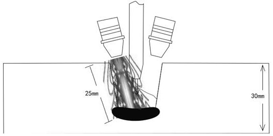
[0009] Alternating ultrasonic field-assisted narrow gap welding technology can not only make the arc reciprocate to the side wall, but also compress the arc and increase the energy density of the arc through the coupling effect of ultrasound and arc, thereby improving the penetration depth of the side wall. The research at home and abroad is still blank. , to ensure that the ultrasonic field can effectively control the deflection of the arc to both side walls, compress the arc, increase the energy density of the arc to improve the penetration depth of the side wall, and use this method to effectively solve the key problem of narrow gap side wall refractory

Method used


Image

  • Alternating ultrasonic field assisted narrow gap welding method
  • Alternating ultrasonic field assisted narrow gap welding method
  • Alternating ultrasonic field assisted narrow gap welding method

Examples


Embodiment Construction

[0034] The present invention will be further described below in conjunction with the accompanying drawings and embodiments.

[0035] The structures, proportions, sizes, etc. shown in the drawings attached to this specification are only used to match the content disclosed in the specification for the understanding and reading of those who are familiar with this technology, and are not used to limit the conditions for the implementation of the present invention , so it has no technical substantive meaning, and any modification of structure, change of proportional relationship or adjustment of size shall still fall within the scope of the disclosure of the present invention without affecting the functions and objectives of the present invention. The technical content must be within the scope covered.

[0036] Such as Figure 1-Figure 4 As shown, the alternating ultrasonic field assisted narrow gap welding method, the steps are as follows:

[0037] Step 1. Determine the device p...


PUM


Abstract

The invention discloses an alternating ultrasonic field assisted narrow gap welding method. The alternating ultrasonic field assisted narrow gap welding method comprises the following steps of 1) placing a machined welded workpiece on a welding platform, beveling the welded workpiece, pressing four corners, correspondingly placing an ultrasonic device on each of the two sides above a groove, correspondingly pointing the lower ends of ultrasonic generators to the other opposite side of the groove, and arranging an electrode between the two ultrasonic devices; 2) welding, specifically, enabling the left and right ultrasonic devices to alternately work to promote the electric arc to swing left and right; (3) in a welding process, adjusting power and frequency parameters of the ultrasonic devices, changing arc deflection amplitude, and enabling arc parameters to reasonably match with the ultrasonic parameters; and (4) after completing welding, closing the system, air-cooling to room temperature, wiping cleanly, and completing welding. According to the alternating ultrasonic field assisted narrow gap welding method, it is guaranteed that an ultrasonic field can effectively control arc deflection, the arc is compressed, arc energy is enhanced, and the key problem that the side wall of the narrow gap is difficult to melt is effectively solved.

Description

technical field [0001] The invention relates to a metal narrow gap welding method, in particular to an alternating ultrasonic field assisted narrow gap welding method. Background technique [0002] With the increasing application of thick plates in metal components such as deep-sea engineering, ships, thick-walled pipelines, and pressure vessels, higher requirements are placed on the welding efficiency and quality of thick plates. The traditional welding method requires a large-angle V-groove, which will cause problems such as large welding filling, large joint deformation and low welding efficiency. Narrow-gap welding technology has the advantages of high welding efficiency, less welding material consumption and low heat input due to the use of narrow and deep small-angle U-shaped or I-shaped grooves, and the advantages of narrow-gap welding increase with the increase of plate thickness obvious. [0003] Although narrow-gap welding has many advantages, due to the small-an...

Claims


Application Information

Patent Timeline
IPC IPC(8): B23K28/02
CPCB23K28/02
Inventor 何欢李玲冰徐晓光叶梦
Owner YANTAI UNIV
Learn More