


Quick Research
Generate reliable direction feasibility study reports for your R&D in just a few steps.

Technical Q&A
Discover and master advanced knowledge NOW. Basics, ideas, possibilities, all at once.

Find Solutions
As an expert in R&D theories, this can generate solutions to your technical problems instantly.

Evaluate Feasibility
Analyze your overall solution with one click, know your potential R&D risks in advance.

Monitor Landscape
Get weekly tech updates, stay abreast of the latest tech innovations and key insights.
Pulse oxygen saturation detector for medical nursing
A saturation and detector technology, used in applications, medical science, diagnostic recording/measurement, etc., to solve problems such as controlling clamping force, inconvenient detection, and the influence of light-emitting modules
- Summary
- Abstract
- Description
- Claims
- Application Information
AI Technical Summary
Problems solved by technology
Method used
Image

Examples
Embodiment 1
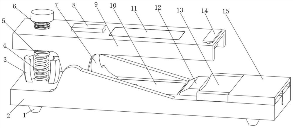
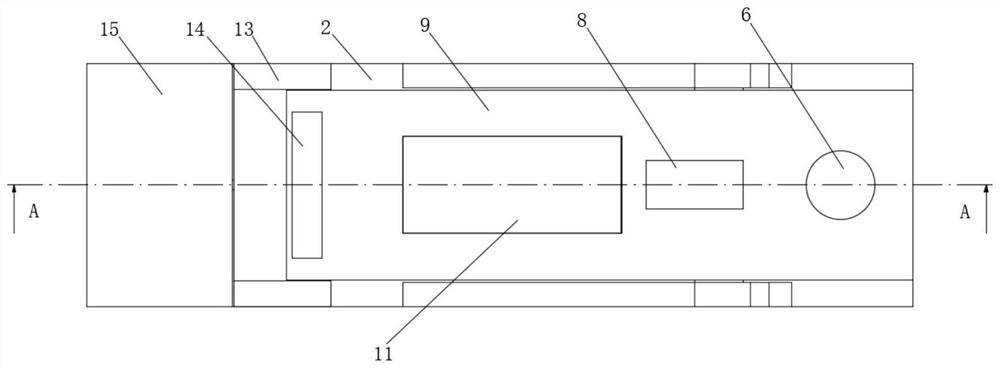
[0024] Embodiment 1: A pulse oximeter for internal medicine nursing, including a base 2 and a transposition 9;
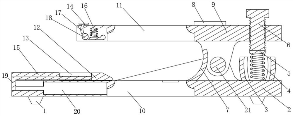
[0025] Base 2: The upper end rotates through the central axis 21, the middle end of the base 2 passes through the light-emitting module 10, the right end of the base 2 is fixed with an electric push rod 20, and the output end of the electric push rod 20 passes through the right side of the base 2 A transmission frame 19 is fixed on the side, and the upper end of the transmission frame 19 is located above the right end of the base 2. The upper end of the transmission frame 19 is fixed with a cleaning block 12. The cleaning block 12 is arranged correspondingly to the left and right sides of the light-emitting module 10, and the transmission frame is driven by an electric push rod 20. 19 moves left and right, and the transmission frame 19 drives the cleaning block 12 to move left and right, so that the cleaning block 12 cleans the surface of the light-emitting module 10...
Embodiment 2
[0029] The difference between this embodiment and Embodiment 1 is:
[0030] In the present embodiment, also include palm holder 15, palm holder 15 is fixed on the upper right end of base 2, and the upper end of drive frame 19 is positioned at the lower end of palm holder 15, can support patient's body by palm holder 15. The palm also includes a finger holder 13, the finger holder 13 is fixed on the upper right end of the base 2, the upper end of the drive frame 19 moves through the finger holder 13, and the finger holder 13 is positioned at the right left of the palm holder 15, The finger rest 13 is located directly below the finger arc pressing plate 17. The finger rest 13 can prevent the patient's fingers from contacting the transmission frame 19, and provide a support platform for the fingers to be placed between the cleaning block 12 and the light emitting module 10, so as to avoid the fingers from being placed on the drive frame 19. The finger is bent by being supported b...
Embodiment 3
[0032] The difference between this embodiment and embodiment two is:
[0033]In this embodiment, it also includes a limiting arc plate 3. There are two limiting arc plates 3 and they are arranged symmetrically. The two limiting arc plates 3 are fixed on the upper left end of the base 2. The first spring 4 is located 3, by limiting the arc plate 3, the left end of the swivel seat 9 is prevented from moving down too much, and the first spring 4 is prevented from being too bent and deformed, and the arc plate 7 is also included, and the arc plate 7 is fixed on the On the upper side of the middle end of the base 2, the finger-arcing plate 7 is located between the central axis 14 and the light-emitting module 10. The finger-arcing plate 7 provides a standard point for placing the user's finger. It also includes a roller 18, which passes through the rotating shaft Rotate in the right end of finger arc pressing plate 17, and press finger arc pressing plate 17 to scratch fingers when ...
PUM
 Abstract
Description
Claims
Application Information
 - R&D Engineer
- R&D Manager
- IP Professional
- Industry Leading Data Capabilities
- Powerful AI technology
- Patent DNA Extraction
Browse by: Latest US Patents, China's latest patents, Technical Efficacy Thesaurus, Application Domain, Technology Topic, Popular Technical Reports.
© 2024 PatSnap. All rights reserved.Legal|Privacy policy|Modern Slavery Act Transparency Statement|Sitemap|About US| Contact US: help@patsnap.com