Automatic winding device and method for micro motor coil

A technology of automatic winding and micro motor, which is applied in the field of motor winding, can solve the problems of poor winding effect and low winding efficiency, and achieve the effect of increasing the blowing area and improving the winding effect and efficiency

Active Publication Date: 2021-07-02
深圳市磐锋精密技术有限公司
View PDF5 Cites 1 Cited by
  • Summary
  • Abstract
  • Description
  • Claims
  • Application Information

AI Technical Summary

Problems solved by technology

[0003] The purpose of the present invention is to provide a kind of automatic winding equipment and winding method for micro-motor coils. It has the ability to fix the rotor through the driving mechanism, and then drive the rotor to rotate. At the same time, under the action of the transmission mechanism, it drives the enameled wire along the The axial reciprocating movement of the rotor in the axial direction can make the enameled wire reciprocate evenly on the surface of the rotor, which improves the winding effect and efficiency, and solves the problem that the winding of the motor coil is manually wound, and its winding efficiency is low , the problem of poor winding effect

Method used


Image

  • Automatic winding device and method for micro motor coil
  • Automatic winding device and method for micro motor coil
  • Automatic winding device and method for micro motor coil

Examples


Embodiment Construction

[0025] The following will clearly and completely describe the technical solutions in the embodiments of the present invention with reference to the accompanying drawings in the embodiments of the present invention. Obviously, the described embodiments are only some, not all, embodiments of the present invention. Based on the embodiments of the present invention, all other embodiments obtained by persons of ordinary skill in the art without making creative efforts belong to the protection scope of the present invention.

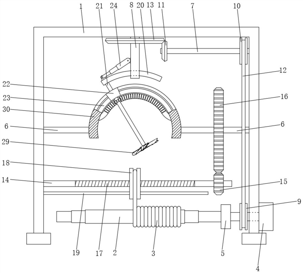
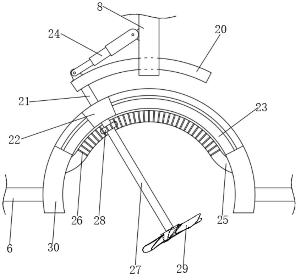
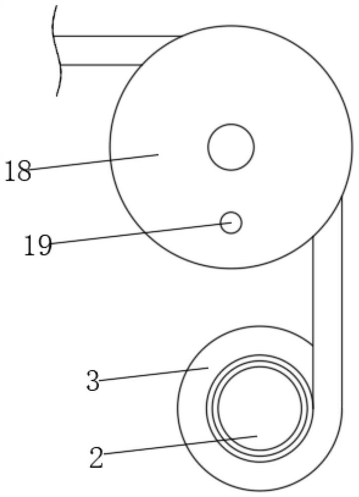
[0026] see Figure 1 to Figure 4 , the present invention provides a technical solution: a micro motor coil automatic winding equipment, including a support frame 1, and also includes a drive mechanism and a transmission mechanism for fixing and driving the rotor 2 to rotate, through the operation of the drive mechanism, and Under the action of the transmission mechanism, the enameled wire 3 is driven to reciprocate axially along the axial direction of the roto...


PUM


Abstract

The invention discloses an automatic winding device and method for a micro motor coil, and relates to the technical field of motor winding. The device comprises a support frame, a driving mechanism and a transmission mechanism; the driving mechanism and the transmission mechanism are used for fixing and driving a rotor to rotate, and under the action of the transmission mechanism, the operation of the driving mechanism drives the enamelled wire to axially reciprocate in the axial direction of the rotor. The device also comprises an adjusting mechanism which is used for adjusting the axial reciprocating distance of the enamelled wire. The device has the advantages that the rotor is fixed through the driving mechanism, then the rotor is driven to rotate, and meanwhile, under the action of the transmission mechanism, the enameled wire is driven to axially reciprocate in the axial direction of the rotor, so the enameled wire can be uniformly wound on the surface of the rotor in a reciprocating manner, and the winding effect and efficiency are improved; the problems that the winding efficiency is low and the winding effect is poor due to the fact that the motor coil is wound manually are solved.

Description

technical field [0001] The invention relates to the technical field of motor winding, in particular to an automatic winding device and a winding method for micro motor coils. Background technique [0002] At present, in the manufacturing process of the motor, the winding of the motor coil is the most important link. The quality of the winding quality of the motor coil and the winding efficiency of the motor coil directly affect the quality of the motor and the production efficiency of the motor. The winding of the coil adopts manual winding, and its winding efficiency is low, and the winding effect is poor. Contents of the invention [0003] The purpose of the present invention is to provide a kind of automatic winding equipment and winding method for micro-motor coils. It has the ability to fix the rotor through the driving mechanism, and then drive the rotor to rotate. At the same time, under the action of the transmission mechanism, it drives the enameled wire along the...

Claims


Application Information

Patent Timeline
Patent Type & Authority Applications(China)
IPC IPC(8): H02K15/00H02K15/08B08B5/02
CPCH02K15/00H02K15/08B08B5/02
Inventor 欧文灏徐思通鲁伟赵阳李文科
Owner 深圳市磐锋精密技术有限公司
Why Eureka
Try Eureka