
Photovoltaic power generation physical reference control method

A technology for photovoltaic power generation and photovoltaic cells

Pending Publication Date: 2021-07-02
朱仁庆
View PDF0 Cites 1 Cited by
  • Summary
  • Abstract
  • Description
  • Claims
  • Application Information

AI Technical Summary

Problems solved by technology

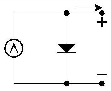
[0004] A simplified circuit model of a photovoltaic cell is figure 2 As shown, the corresponding mathematical model is Among them: I L is the photogenerated current, I S is the reverse saturation current, the ideal constant A usually takes 1~2, U T =KT / q, T is the thermodynamic temperature, Boltzmann constant K=1.38*10 -23 J / K, charge q=1.6*10 -19 C, U at room temperature T ≈26mV; It can be seen that the volt-ampere characteristics of photovoltaic cells are nonlinear. Since the photo-generated current and parameters inside photovoltaic cells will change with changes in light intensity and ambient temperature, it is difficult to control photovoltaic power generation to achieve maximum power output.
[0005] At present, the monitoring of the working state of photovoltaic cells and the preset algorithm of the controller are used to adjust the load rate to achieve the maximum power output of photovoltaic power generation. The circuit diagram is as follows image 3 As shown, although the circuit structure of this method is relatively simple, the control algorithm is more complex, the optimization speed is slow, the effect is poor when the weather changes rapidly, and sometimes even stability problems occur

Method used


Image

  • Photovoltaic power generation physical reference control method
  • Photovoltaic power generation physical reference control method
  • Photovoltaic power generation physical reference control method

Examples


Embodiment 1

[0056] Photovoltaic power generation system with simple physical reference control

[0057] The photovoltaic power generation system with simple physical reference control is mainly composed of a working photovoltaic cell, two reference photovoltaic cells, a controller and a load, such as Figure 4 As shown, the working photovoltaic cell is connected to the energy input port of the controller, and the energy output port of the controller is connected to the load.

[0058] The reference photovoltaic cell adopts A and B two monolithic objects of the same quality as the working photovoltaic cell. Block A is used to measure the open circuit voltage, and block B is used to measure the short-circuit current. The reference photovoltaic cell is placed near the working photovoltaic cell. The reference photovoltaic cell Connect with the signal input port of the controller through the controlled source.

[0059] Measurement of the open circuit voltage of the reference photovoltaic cell ...

Embodiment 2

[0064] Photovoltaic power generation system with mean value physical reference control

[0065] The photovoltaic power generation system with reference to the fixed average measurement algorithm in kind is mainly composed of working photovoltaic cells, reference photovoltaic cells, controllers and loads, such as Figure 6 As shown, the working photovoltaic cell is connected to the energy input port of the controller, and the energy output port of the controller is connected to the load.

[0066] The reference photovoltaic cell adopts A, B, C, and D four pieces of monolithic objects of the same quality as the working photovoltaic cell. A block is used to measure the open circuit voltage, B block is used to measure the short circuit current, and C block is used to measure α = 80% open circuit The current at voltage and block D are used to measure the voltage at the time of β=80% short-circuit current. The reference photovoltaic cell is placed near the working photovoltaic cell, ...

Embodiment 3

[0074] Photovoltaic power generation system with scanning object reference control

[0075] The photovoltaic power generation system with scanning physical reference control is composed of working photovoltaic cells, reference photovoltaic cells, controllers and loads. The voltage scanning method is as follows: Figure 9a As shown, the current sweep method is as Figure 9b As shown, the working photovoltaic cell is connected to the energy input port of the controller, and the energy output port of the controller is connected to the load.

[0076] Voltage scanning method: the reference photovoltaic cell adopts A and C two single-chip objects of the same quality as the working photovoltaic cell, A block is used to measure the open circuit voltage, and C block is used to measure the current during voltage scanning, and the reference photovoltaic cell is placed on the working photovoltaic cell Nearby, the reference photovoltaic cell is connected to the signal input port of the co...


PUM


Abstract

The invention relates to a photovoltaic power generation physical reference control method, in particular to a control method adopting physical reference, and belongs to the field of photovoltaic power generation or optimal control methods. The photovoltaic power generation real object reference control method realizes the maximum output power of the photovoltaic cell. According to the first method, the open-circuit voltage and the short-circuit current of the reference photovoltaic cell are measured, the optimal reference resistance is calculated, and the working photovoltaic cell is controlled to reach the maximum output power. The second method comprises the following steps: measuring the open-circuit voltage and the short-circuit current of the reference photovoltaic cell, measuring the current at 80% of the open-circuit voltage and the voltage at 80% of the short-circuit current, calculating the optimal reference resistance, and controlling the working photovoltaic cell to reach the maximum output power. The third method comprises the following steps: measuring the open-circuit voltage or short-circuit current of the reference photovoltaic cell, scanning in a range of 50%-100% of the open-circuit voltage or short-circuit current, measuring the current or voltage at the same time, calculating the voltage and current or optimal reference resistance when the maximum output power is recorded, and controlling the working photovoltaic cell to reach the maximum output power.

Description

technical field [0001] The invention relates to a photovoltaic power generation physical reference control method, in particular to a control method using physical reference instead of model reference, and belongs to the field of photovoltaic power generation or optimal control methods. Background technique [0002] Green and environmentally friendly photovoltaic power generation is one of the important development directions of clean energy. [0003] Photovoltaic power generation converts solar energy into electrical energy. An important technology is to emit as much electrical energy as possible under the same light conditions. The simple circuit model and common circuit model of photovoltaic cells are as follows: Figure 1a , 1b shown. [0004] A simplified circuit model of a photovoltaic cell is figure 2 As shown, the corresponding mathematical model is Among them: I L is the photogenerated current, I S is the reverse saturation current, the ideal constant A usual...

Claims


Application Information

Patent Timeline
Patent Type & Authority Applications(China)
IPC IPC(8): G05F1/67G05B13/04
CPCG05B13/042G05F1/67Y02E10/56
Inventor 朱明朱仁庆贺新宇
Owner 朱仁庆
Learn More