
High-voltage device for double-flow system rail transit vehicle

A technology for rail transit vehicles and high-voltage devices, applied in the field of rail transit, can solve problems such as the inability to guarantee the safety performance, the inability to obtain electricity from the pantograph, and the inability to adapt to the electrical requirements of the dual-stream system.

Pending Publication Date: 2021-07-02
CHONGQING CRRC RAILWAY VEHICLES CO LTD
View PDF10 Cites 0 Cited by
  • Summary
  • Abstract
  • Description
  • Claims
  • Application Information

AI Technical Summary

Problems solved by technology

Rail transit vehicles in the prior art take power from a single AC or DC catenary, and the pantograph cannot switch between DC or AC catenary to take power
Therefore, the current high-voltage device can only adapt to the situation of taking power from a single AC or DC catenary, and on a dual-current rail transit vehicle, due to the different voltages of the AC catenary and the DC catenary and the difference in current The flow is different, so the current high-voltage device cannot meet the electrical requirements of the dual-current system, especially the safety performance of the current high-voltage device cannot be guaranteed

Method used


Image

  • High-voltage device for double-flow system rail transit vehicle
  • High-voltage device for double-flow system rail transit vehicle
  • High-voltage device for double-flow system rail transit vehicle

Examples


Embodiment Construction

[0028] The following is further described in detail through specific implementation methods:

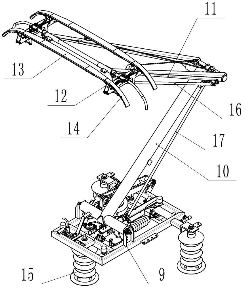
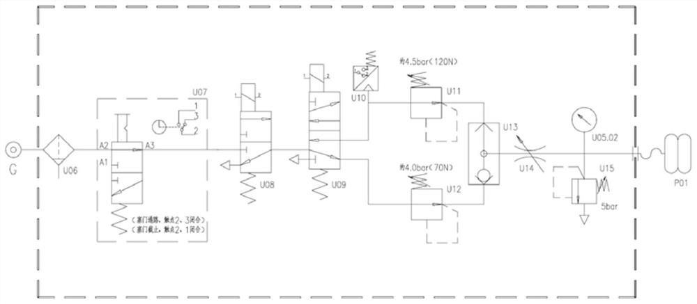
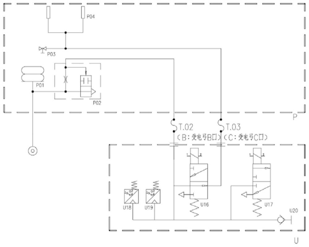
[0029] The reference signs in the drawings of the description include: high voltage cable 1, rigid terminal 2, half clip 3, flange 4, gasket 5, sealing ring 6, label 7, sealing cap 8, chassis assembly 9, lower arm assembly 10. Upper arm assembly 11, bow head assembly 12, bow head 13, bow angle 14, insulator 15, upper guide rod 16, lower guide rod 17, box body 18, box cover 19, hydraulic rod 20, vacuum circuit breaker 21, AC DC voltage transformer 22, filter U06, electric signal plate plug door U07, bow solenoid valve U08, electromagnetic reversing valve U09, third pressure switch U10, first precision pressure regulating valve U11, second precision pressure regulating valve U12 , Shuttle valve U13, Throttle valve U14, Safety valve U15, Air bag P01, Rapid lowering valve P02, ADD test valve P03, Slider P04, ADD fault recovery valve U16, Rapid exhaust valve U17, First pressure switch U18...


PUM

PropertyMeasurementUnit
Heightaaaaaaaaaa

Abstract

The invention relates to the field of rail transit, in particular to a high-voltage device for a double-current system rail transit vehicle, which comprises a pantograph, a high-voltage box and a high-voltage cable, and is characterized in that the pantograph comprises an underframe assembly, a pantograph lifting mechanism, an insulator, a lower arm assembly, a lower guide rod, an upper arm assembly, an upper guide rod and a pantograph head assembly; the insulator is mounted at the bottom of the underframe assembly; the pantograph lifting mechanism is installed on the underframe assembly, the lower arm assembly is connected between the upper arm assembly and the pantograph lifting mechanism, and the pantograph head assembly is installed at the end, away from the lower arm assembly, of the upper arm assembly; the pantograph lifting mechanism comprises an air bag and a steel wire rope, the lower arm assembly comprises a lower arm, and the steel wire rope is connected between the lower arm assembly and the air bag. Compared with the prior art, the high-voltage device can be used under a double-current working condition, and the electrical safety is ensured. The high-voltage box comprises a high-voltage box body, a vacuum circuit breaker and an alternating-current and direct-current voltage transformer. The technical problem that the vacuum circuit breaker cannot be arranged due to insufficient space of the double-current system rail transit vehicle is mainly solved.

Description

technical field [0001] The invention relates to the field of rail transit, in particular to a high-voltage device for dual-stream rail transit vehicles. Background technique [0002] During the running of the rail train, it needs to continuously obtain electric energy from the catenary through the high-voltage device, so as to provide energy for the running of the train. The high-voltage device usually includes a structure such as a pantograph, a high-voltage box and a high-voltage cable assembly. The pantograph is an electrical device that draws current from the catenary for the rolling stock to provide power for the traction power equipment of the train. It includes chassis assembly, Bow raising mechanism, insulator, lower arm assembly, upper arm assembly and bow head assembly; the insulator is installed on the bottom of the bottom frame assembly; the bow raising mechanism is installed on the bottom frame assembly, and the lower arm assembly is connected between the upper ...

Claims


Application Information

Patent Timeline
IPC IPC(8): B60L5/20B60L5/32B60L3/00
CPCB60L5/20B60L5/32B60L3/00
Inventor 胡涵姚鸿洲孙文斌刘正威姚平陈波赵益林张鸿艳
Owner CHONGQING CRRC RAILWAY VEHICLES CO LTD
Learn More