Resin flow zone control method in composite material component

A composite material component and composite material technology, which is applied in the field of resin flow partition control in composite material components, can solve problems such as difficult control of resin flow, and achieve the effect of solving serious uneven curing thickness

Active Publication Date: 2021-07-02
NANJING UNIV OF AERONAUTICS & ASTRONAUTICS
View PDF5 Cites 1 Cited by
  • Summary
  • Abstract
  • Description
  • Claims
  • Application Information

AI Technical Summary

Problems solved by technology

[0006] The purpose of the present invention is to solve the problem that resin flow is difficult to control during the curing process of composite material components, and to invent a method for controlling resin flow partitions in composite material components

Method used


Image

  • Resin flow zone control method in composite material component
  • Resin flow zone control method in composite material component
  • Resin flow zone control method in composite material component

Examples


example 1

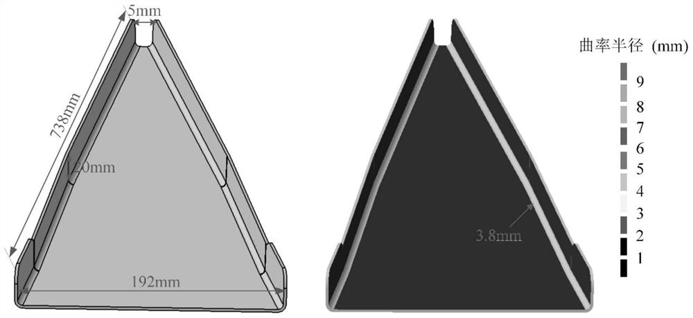
[0035]The embodiment of the present invention is described by taking a typical variable-section aircraft composite material component as an example. The length of the component is 738mm, the height is 20mm, and the thickness is 2mm. The section width decreases from 192mm to 5mm with the length, such as image 3 shown. By analyzing the resin pressure distribution of the component, according to the first partition criterion, the component is divided into 5 areas: 2 arc areas and 3 plane areas. According to the second division criterion, the radius of curvature corresponding to the resin pressure threshold is 27mm, and the radius of curvature of the two arcs is 3.8mm, both of which are lower than 27mm. There is no need to divide the already divided areas. The final division result of this component is 5 areas.

[0036] Microfluidic valves are arranged at the boundaries of the five regions to limit the mutual flow of resin between different regions. Two rows of micropores with a...

example 2

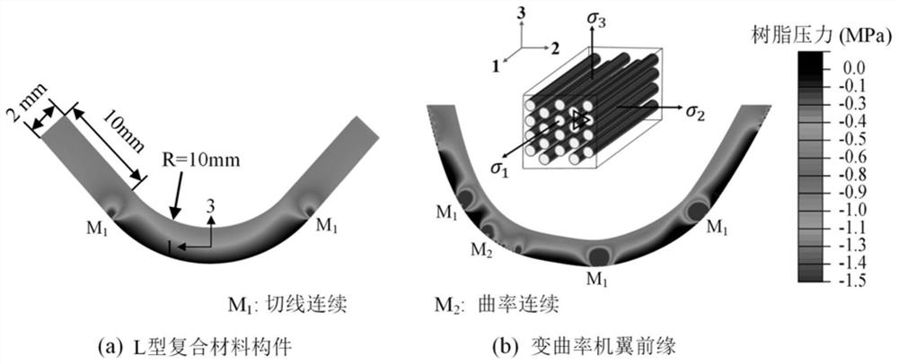
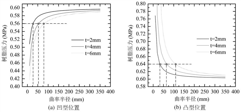
[0038] The difference between this example and Example 1 is that the resin pressure in the profile of the composite component is continuous, and after the first partition criterion is invalid, the profile surface is continued to be divided according to the second partition criterion. Component shape such as Figure 4 As shown, the thickness of the composite material is 2 mm. According to the content of the invention, if the resin pressure loss of 0.04 MPa is used as the threshold value, the corresponding radius of curvature at the concave position is 27 mm, and the corresponding radius of curvature at the convex position is 35 mm. According to the second division criterion, the The component is finally divided into 9 areas, and the rest are the same as Example 1.


PUM

PropertyMeasurementUnit
thicknessaaaaaaaaaa

Abstract

A resin flow zone control method in a composite material component is characterized in that the composite material component is divided into a plurality of areas with close resin pressure according to resin pressure distribution in a composite material, micro-flow valves are arranged on the boundary of the areas, mutual flow of resin between different areas is limited, complex flowing in the component is converted into independent flowing in the areas, large-range flowing of resin under the action of pressure difference in the curing process of the composite material component is avoided, and the curing thickness of the composite material component with the complex profile is effectively controlled. The method solves the problem that resin flow is difficult to control in the curing process of the composite material component with the complex profile, and has the advantages of being easy to operate, good in control effect and the like.

Description

technical field [0001] The invention relates to composite material forming technology, especially resin flow control technology in components during composite material forming process, in particular to a resin flow zone control method in composite material components. Background technique [0002] Fiber-reinforced resin-based composites have excellent properties such as high specific strength, high specific modulus, fatigue resistance, and corrosion resistance. After nearly 40 years of development, composite materials are widely used in aviation and other fields, greatly reducing the structural weight of aircraft, shortening the manufacturing cycle, and developing from the initial application of secondary load-bearing components to the application of fuselage bulkheads, wing spars, etc. Large main bearing member. [0003] In actual production, especially for composite components with complex shapes, there is a common problem that the solidified thickness is difficult to con...

Claims


Application Information

Patent Timeline
Patent Type & Authority Applications(China)
IPC IPC(8): B29C70/34B29C70/54
CPCB29C70/342B29C70/54
Inventor 李迎光何永喜郝小忠文友谊
Owner NANJING UNIV OF AERONAUTICS & ASTRONAUTICS
Why Eureka
Try Eureka