Magnetism gathering type direct-driven permanent magnet motor

A permanent magnet motor and magnetism-concentrating technology, which is applied in the field of magnetism-concentrating direct-drive permanent magnet motors, can solve the problems of short motor life, high additional cost for installation and transportation, and high cost, and achieve high-strength load performance and magnetism-concentrating effect Visible, easy to install and reliable results

Active Publication Date: 2021-06-29
SUZHOU SEIDAL INTELLIGENT TECH CO LTD
View PDF7 Cites 3 Cited by
  • Summary
  • Abstract
  • Description
  • Claims
  • Application Information

AI Technical Summary

Problems solved by technology

[0005] (1) The price is extremely expensive: because the main components of permanent magnets are NdFeB or SmCo, which are rare earth materials, the cost is high and scarce, and the stator is covered with rare earth permanent magnets, which are extremely expensive when used in long-stroke occasions
[0006] (2) The additional cost of installation and transportation is high: the permanent magnet will generate a strong magnetic field around it, and a special magnetic isolation shield is required in the production process of the stator, which further increases the cost
[0007] (3) The life of the motor is short: the strong magnetic field on the stator will attract iron filings and dust into the motor when the motor is running, affecting the life of the motor
Although some manufacturers will take measures to prevent dust, such as using shielding covers, organ covers and other dust-proof measures, this will undoubtedly increase the cost of the motor
[0008] (4) Generate electromagnetic interference: the permanent magnet on the stator will generate a strong magnetic field around it, which will interfere with the normal operation of the surrounding electronic components, resulting in limited application in the precision detection field of the 3C industry
[0009] (5) High potential safety hazard: If the powerful permanent magnet is not properly operated during the handling, installation and use of the motor, it will cause workers to be injured

Method used


Image

  • Magnetism gathering type direct-driven permanent magnet motor
  • Magnetism gathering type direct-driven permanent magnet motor
  • Magnetism gathering type direct-driven permanent magnet motor

Examples


Embodiment Construction

[0024] In order to make the technical means, creative features, goals and effects achieved by the present invention easy to understand, the present invention will be further described below in conjunction with a specific implementation example of the present invention.

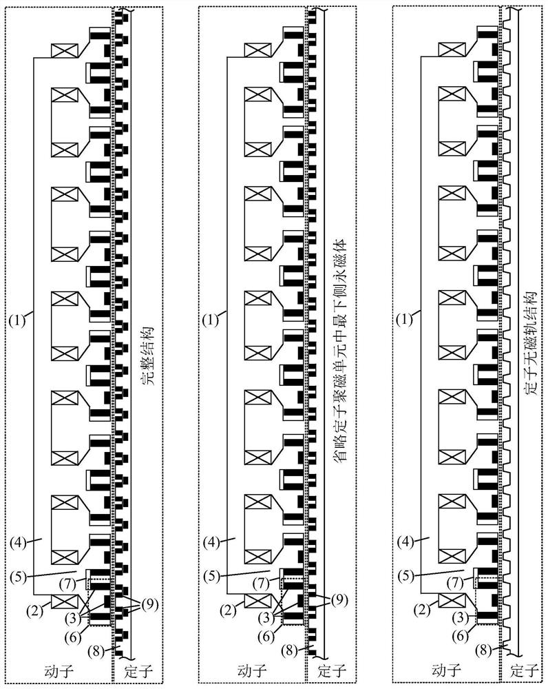
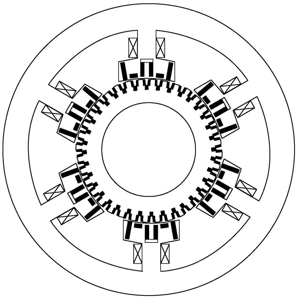
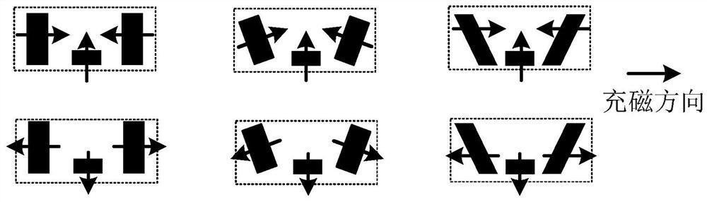
[0025] A magnetism-concentrating direct-drive permanent magnet motor, comprising two major components of a mover and a stator, characterized in that the mover includes a mover iron core (1), a winding (2), and a mover permanent magnet (3), wherein The iron core of the mover is made of soft magnetic material, which is composed of several mover teeth (4) connected through the mover yoke (5). Two sets of mover magnetic gathering units (6) are installed on the mover teeth. The magnetism gathering unit is located at the pole shoe of the mover teeth, each mover magnet collection unit contains three mover permanent magnets and soft magnetic material for fixing its installation position, the magnetization direction of ...


PUM


Abstract

The invention discloses a magnetism gathering type direct-drive permanent magnet motor which mainly structurally comprises a rotor and a stator and can be a linear motor or a rotary motor. The motor is mainly characterized in that a plurality of permanent magnets in the rotor iron core and the stator iron core are mounted in a specifically designed mounting mode and magnetizing directions, and the rotor and the stator are assembled at specific relative positions, so that the magnetism gathering effect of the plurality of permanent magnets is remarkable, and a relatively high permanent magnetic field utilization rate and a relatively small magnetic leakage coefficient are obtained; and therefore, the thrust density is obviously increased. The magnetism gathering type direct-drive permanent magnet motor has the advantages of being high in thrust density, small in thrust fluctuation, low in cost, easy to machine and assemble, reliable in operation, easy to expand multiple modules and the like.

Description

technical field [0001] The invention relates to the technical field of permanent magnet synchronous linear motors, in particular to a magnetism-concentrating direct-drive permanent magnet motor. Background technique [0002] This application claims the priority of citing the following patent: a magnetism-concentrating type non-magnetic track linear motor (2021100157351). [0003] In recent years, with the rapid development of high-end machine tools, 3C industry, laser cutting, liquid crystal panel, and lithium battery industry, for high-speed, high-precision, and long-stroke linear travel applications, sliding linear machines based on screw or belt drive The motion system has been difficult to meet the needs of practical applications. Linear motors can directly generate linear motion based on the working principle of traditional rotary motors. They are suitable for working conditions such as long strokes, high precision, high dynamic response, and long life. They have becom...

Claims


Application Information

Patent Timeline
Patent Type & Authority Applications(China)
IPC IPC(8): H02K1/06H02K1/12H02K41/03
CPCH02K41/031H02K41/033H02K1/06H02K1/12
Inventor 顾聪盛田田张云龙石腾瑞
Owner SUZHOU SEIDAL INTELLIGENT TECH CO LTD
Why Eureka
Try Eureka