Cable roundness shaping and positioning device
A positioning device and roundness technology, applied in the direction of conductor/cable insulation, etc., can solve the problem of inconvenient adjustment of the height of the adjustment device
- Summary
- Abstract
- Description
- Claims
- Application Information
AI Technical Summary
Problems solved by technology
Method used
Image
Examples
Embodiment 1
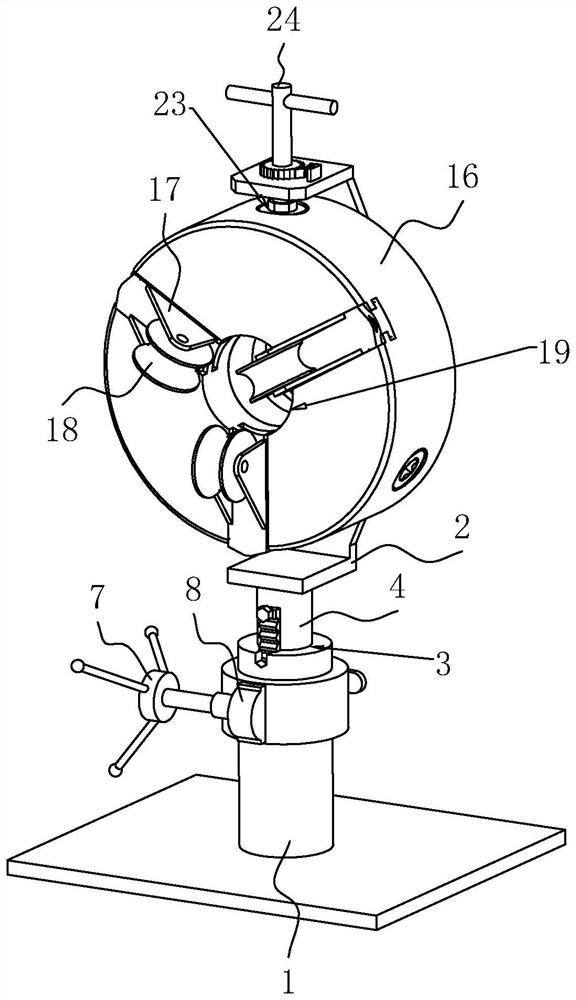
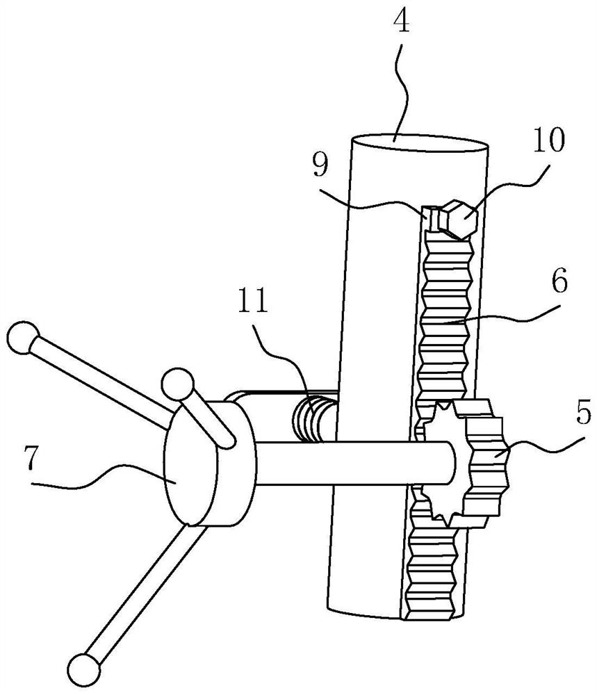
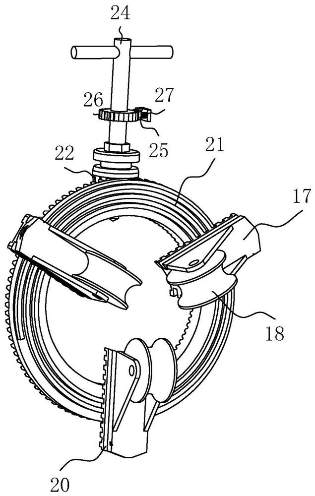
[0040] The embodiment of the present application discloses a cable roundness shaping and positioning device. refer to figure 1 and figure 2 , a cable roundness shaping and positioning device includes a support base 1 and a support 2 arranged up and down with the support base 1, the support 2 is provided with an adjustment device, and the adjustment device is used for leveling the surface of the core body. The center of the support base 1 A sliding hole 3 is provided, and the bracket 2 is fixedly connected with a sliding rod 4 slidably connected in the sliding hole 3. Lubricating oil is filled between the sliding rod 4 and the inner wall of the sliding hole 3, and the support seat 1 is provided with a drive for driving the sliding rod 4 to move. device.
[0041] refer to figure 1 and figure 2 , the driving device includes a first gear 5, a first rack 6 and a power member, the first gear 5 is rotationally connected with the support base 1, the central axis of the first gea...
Embodiment 2
[0052] refer to Figure 4 and Figure 5 The difference between Embodiment 1 and Embodiment 2 lies in the driving device. The driving device includes a driving sleeve 12 that is rotatably connected with the support base 1, a screw rod 13 that is threadedly connected with the driving sleeve 12, and a stopper that restricts the rotation of the sliding rod 4. The screw rod 13 is connected to the sliding rod 4. The rod 4 is fixedly connected, the top of the screw rod 13 is fixedly connected with the bracket 2, the screw rod 13 is slidably connected in the slide hole 3, the driving sleeve 12 is provided with an internal thread, and the rotation between the bottom of the driving sleeve 12 and the support seat 1 is realized through the shaft sleeve; The position piece is set to 14 limit blocks, the limit block 14 is fixedly connected with the inner wall of the slide hole 3, and the 4 peripheral walls of the slide bar are provided with a limit groove 15 (such as Figure 6 As shown), t...
PUM
 Abstract
Description
Claims
Application Information
 - R&D
- Intellectual Property
- Life Sciences
- Materials
- Tech Scout
- Unparalleled Data Quality
- Higher Quality Content
- 60% Fewer Hallucinations
Browse by: Latest US Patents, China's latest patents, Technical Efficacy Thesaurus, Application Domain, Technology Topic, Popular Technical Reports.
© 2025 PatSnap. All rights reserved.Legal|Privacy policy|Modern Slavery Act Transparency Statement|Sitemap|About US| Contact US: help@patsnap.com


