
A high-frequency response precision force measuring device

A force-measuring device and high-frequency response technology, which is applied in the field of high-frequency-response precision force-measuring devices, can solve the problems that the measurement accuracy cannot reach the disturbance force measurement accuracy, the measurement accuracy cannot be satisfied, and the cost rises, etc., to solve the small measurement range , improve the structural mode, improve the effect of precision

Active Publication Date: 2022-07-01
SHANGHAI MICRO ELECTRONICS EQUIP (GRP) CO LTD
View PDF0 Cites 0 Cited by
  • Summary
  • Abstract
  • Description
  • Claims
  • Application Information

AI Technical Summary

Problems solved by technology

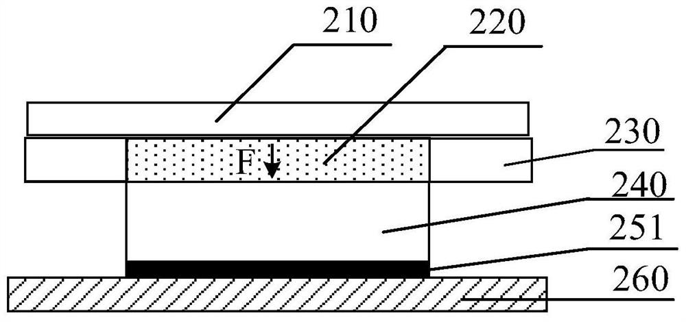
In practical applications, even the high-frequency precision force sensor model 1-U9C / 50N provided by the industry-leading supplier of precision force measurement HBM, according to the relevant data marked in its product manual, although its natural frequency 6.5KHZ can It meets the high frequency requirements, but the measurement accuracy of ±0.05N cannot meet the requirement of disturbance force measurement accuracy ≤±0.04N. In fact, the measurement accuracy can reach ±0.03N through calibration, so the existing online test platform mostly adopts this scheme
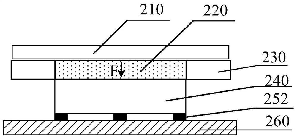
However, for the stability of the overall structure, it is often necessary to arrange a plurality of second force sensors 252 under the force plate 240, for example, in the figure 2 Among them, a total of three second force sensors 252 are used, which will not only increase the cost and lead to a complex structure, but also the measurement accuracy of which accumulates the measurement accuracy of multiple sensors, and finally the measurement accuracy of the entire force measuring device cannot meet ± 0.03N required

Method used


Image

  • A high-frequency response precision force measuring device
  • A high-frequency response precision force measuring device
  • A high-frequency response precision force measuring device

Examples


Embodiment 3

[0054] as attached Image 6 As shown, a schematic diagram of the structure of the high-frequency response precision force measuring device of the present embodiment, the high-frequency response precision force measuring device provided by the present embodiment, compared with the first embodiment, the difference is that the guide structure 270 is Air buoyancy guide, the air buoyancy of the air buoyancy guide acts on the bottom of the force plate 240, so that the force plate 240 is forced under the combined action of its gravity, the fluid medium disturbance force F and the air buoyancy force balance; further, the force measuring assembly includes a pressure sensor 280 and an acceleration sensor 290, the pressure sensor 280 is arranged on the outer side of the guide structure body 271, and is used to monitor the pressure change of CDA (Compressed Dry Air); the The acceleration sensor 290 is arranged on the force plate 240 for monitoring the vertical acceleration of the force pl...


PUM

PropertyMeasurementUnit
diameteraaaaaaaaaa
friction coefficientaaaaaaaaaa

Abstract

The invention provides a high-frequency-response precision force measuring device for immersion lithography equipment, comprising a top structure, an immersion structure, a load-bearing unit, a guide structure, a force-measuring component and a support frame; the top structure is located at the Above the submerged structural member, the fluid medium generates a disturbance force in the flow of the submerged structural member, and the load-bearing unit is located below the submerged structural member; the guiding structure includes a guiding On the periphery of the load-bearing unit, its bottom is fixed with the support frame, and the moving part is located on the side of the guide structure body close to the load-bearing unit; the force-measuring component is in contact with the load-bearing unit to obtain the disturbance force of the fluid medium in the submerged structural member. The high-frequency response precision force measuring device provided by the invention solves the problem of structural stability based on a single sensor, and realizes high-frequency response while ensuring the measurement accuracy.

Description

technical field [0001] The invention relates to a force measuring device for immersion lithography equipment, in particular to a high-frequency response precision force measuring device. Background technique [0002] Modern semiconductor integrated circuit manufacturing is based on optical lithography equipment, which uses an optical system to accurately project the integrated circuit pattern on the reticle onto the target area of ​​the substrate. In the prior art, an immersion lithography apparatus generally uses a 193 nm light source, which can realize the manufacture of integrated circuits at a node of 45 nm and below. The immersion lithography machine is filled with a fluid medium (usually specially treated ultrapure water) between the exposure lens and the substrate, and adopts a light path design that combines refraction and reflection. This design can reduce the number of optical components in the projection system. Controlling aberrations and thermal effects increas...

Claims


Application Information

Patent Timeline
Patent Type & Authority Patents(China)
IPC IPC(8): G01L11/00G01M10/00
CPCG01L11/00G01M10/00
Inventor 余斌罗晋
Owner SHANGHAI MICRO ELECTRONICS EQUIP (GRP) CO LTD
Learn More