Bolt axial force detector for building detection

A bolt shaft and detector technology, applied in force/torque/work measuring instruments, measuring torque/torsional force during tightening, instruments, etc., can solve the problem of not having an adjustment structure when moving, not having a classified storage structure, and reducing building inspection. Use the flexibility of the bolt axial force detector to achieve the effect of reducing resistance and improving flexibility

Active Publication Date: 2021-06-29
广西建宏工程科技有限公司
View PDF8 Cites 0 Cited by
  • Summary
  • Abstract
  • Description
  • Claims
  • Application Information

AI Technical Summary

Problems solved by technology

[0004] Existing bolt axial force detectors for building inspections have certain disadvantages during use. The traditional bolt axial force detectors for building inspections do not have multiple combined fixation The structure makes the traditional bolt axial force tester for building inspection unable to flexibly adapt to different types of bolts, which reduces the flexibility of using the bolt axial force tester for building inspection; secondly, the traditional bolt axial force tester for building inspection does not have the ability to move Adjust the structure, so that the traditional bolt axial force tester for building inspection cannot be flexibly applied to bolt structures of different lengths, which reduces the scope of application of the bolt axial force tester for building inspection; secondly, the traditional bolt axial force tester for building inspection does not have classification The storage structure makes it impossible for the traditional bolt axial force tester for building inspection to perform classified storage operations according to the bolt type, which reduces the functionality of the traditional bolt axial force tester for building inspection and brings certain adverse effects to users

Method used


Image

  • Bolt axial force detector for building detection
  • Bolt axial force detector for building detection
  • Bolt axial force detector for building detection

Examples


Embodiment Construction

[0033] The technical solutions in the embodiments of the present invention will be clearly and completely described below in conjunction with the embodiments of the present invention. Apparently, the described embodiments are only some of the embodiments of the present invention, not all of them. Based on the embodiments of the present invention, all other embodiments obtained by persons of ordinary skill in the art without creative efforts fall within the protection scope of the present invention.

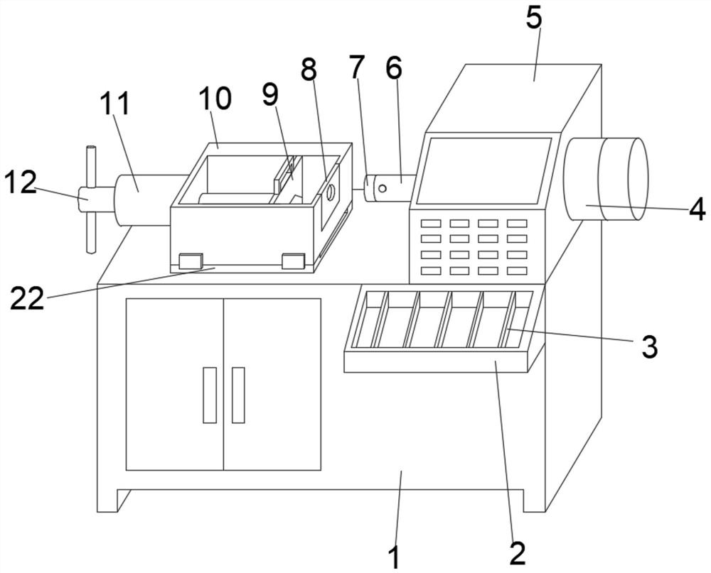
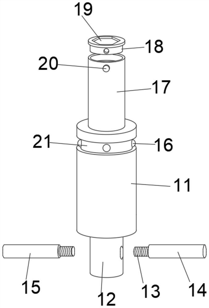
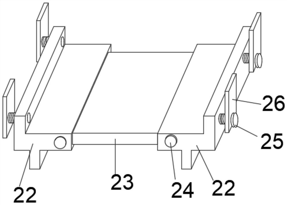
[0034] Such as Figure 1-6 As shown, a bolt axial force tester for building inspection includes a box base 1, a movable card box 10 and a sealing cover 5, the sealing cover 5 is fixedly installed on the upper outer surface of the box base 1, and the mobile card box 10 is movably installed On the side near the sealing cover 5 at the top of the box base 1, a sliding deck 22 is arranged between the moving card box 10 and the box base 1, and the inboard of the moving card box 10 is mo...


PUM


Abstract

A bolt axial force detector for building detection disclosed by the present invention comprises a box body base, a movable clamping box and a sealing cover. The sealing cover is fixedly installed on the outer surface of the upper end of the box body base, the movable clamping box is movably installed on one side, close to the sealing cover, of the upper part of the box body base, and a sliding clamping seat is arranged between the movable clamping box and the box body base. The inner side of the movable clamping box is movably sleeved with a combined clamping plate, the middle position of the inner side of the combined clamping plate is movably sleeved with a splicing clamping plate, first clamping strips are fixedly installed on the outer surfaces of the two sides of the splicing clamping plate, and second clamping strips are fixedly installed on the outer surfaces of the two sides of the combined clamping plate; the movable clamping box and the combined clamping plate are in butt joint and fixed through a second clamping strip; the bolt axial force detector for building detection has a multi-combination structure, can perform any adjustment operation according to the structure of a bolt, improves the flexibility during use, can be suitable for bolts of different models, and is convenient to use.

Description

technical field [0001] The invention belongs to the technical field of axial force detectors, and more specifically relates to a bolt axial force detector for building detection. Background technique [0002] The internal force that coincides with the axis of the rod is called the axial force, which is represented by the symbol FN. When the rod is pulled, the axial force is the tension and it points away from the section. When the rod is compressed, the axial force is the pressure and it points to the section. It is usually stipulated that tension is represented by a positive sign and that pressure is represented by a negative sign. [0003] The patent document CN209992097U discloses a bolt axial force detector for building detection, which includes a box body. A bearing is installed throughout, the inner wall of the bearing is fixedly connected with a threaded rod, the right end of the threaded rod extends to the inner cavity of the box body, the surface of the threaded ro...

Claims


Application Information

Patent Timeline
IPC IPC(8): G01L5/24
CPCG01L5/243
Inventor 文川俞百新王伦鹍丁起蕾
Owner 广西建宏工程科技有限公司
Why Eureka
Try Eureka