Steel springboard fixing support and scaffold

A technology for fixing brackets and scaffolding, which is applied in the connection of scaffolding, the attachment of scaffolding, the support of house structure, etc., can solve the problems of poor erection effect of steel springboards, slipping and shaking, hidden dangers, etc., and saves construction time and installation methods. Convenience and improved safety

Active Publication Date: 2021-06-29
CHINA CONSTR SECOND ENG BUREAU LTD
View PDF5 Cites 0 Cited by
  • Summary
  • Abstract
  • Description
  • Claims
  • Application Information

AI Technical Summary

Problems solved by technology

[0002] Scaffolding can be seen everywhere in engineering construction. Multiple steel springboards are overlapped end-to-end along the length of the scaffolding and erected on the scaffolding as a construction operation platform for workers to pass. The current steel springboards do not work well and often occur during use. The problem of slipping and shaking has certain potential safety hazards

Method used


Image

  • Steel springboard fixing support and scaffold
  • Steel springboard fixing support and scaffold
  • Steel springboard fixing support and scaffold

Examples


Embodiment 1

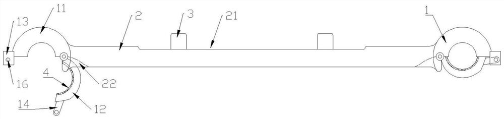
[0040] A steel springboard fixing bracket, the steel springboard is easy to install, can effectively fix the steel springboard, saves the installation period and improves the use safety of the steel springboard, such as figure 1 , figure 2 , image 3 , Figure 4 As shown, specifically set to the following structure:

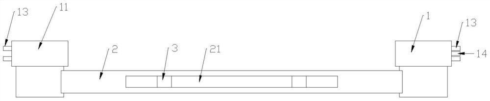
[0041] This kind of steel springboard fixing bracket includes a steel pipe holding card 1 and a connecting cross bar 2;

[0042]Specifically, the steel pipe holding card 1 includes a holding card main body 11 , a valve 12 , a lock head 13 and a dead bolt 14 . The main body 11 for holding the card is roughly a semi-circular structure, the bottom of which has a semi-circular groove with a notch downward, and the outer side of the main body 11 for holding the card is fixedly connected with a lock head 13 . The valve 12 is roughly a semi-circular structure, and its top has an arc groove with a notch upward, and the arc groove is larger than the semicircle groove...

Embodiment 2

[0047] This embodiment is further optimized on the basis of the above-mentioned embodiments, further to better realize the present invention, especially adopt the following configuration structure:

[0048] The top of the connecting cross bar 2 is provided with a concave flat groove 21, and a vertically protruding stopper 3 is fixedly connected in the flat groove 21, and the height of the stopper 3 is greater than the groove depth of the flat groove 21 and The sum of the plate thicknesses of steel springboards. The limit protrusion 3 is used to pass through the limit hole provided on the steel springboard 6 to limit it longitudinally, so as to improve the use safety of the steel springboard.

[0049] Preferably, the quantity of the limiting protrusions 3 is set to be multiple, and all the limiting protrusions 3 are arranged in sequence along the length direction of the connecting cross bar 2 .

Embodiment 3

[0051] This embodiment is further optimized on the basis of the above-mentioned embodiments, further to better realize the present invention, especially adopt the following configuration structure:

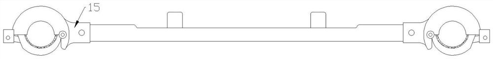
[0052] The inner side of the holding card main body 11 is welded with a transverse intubation tube 15, the intubation tube 15 has a pin hole 16 penetrating in its radial direction, the end of the connecting cross bar 2 has a through hole aligned with the pin hole 16, and the connecting cross bar 2 It is detachably inserted into the cannula 15 at the corresponding end and passed through the bolt for fixing. In this way, the setting of the intubation tube 15 can be used for plugging and connecting the cross bar 2, and the steel springboard fixing bracket can be disassembled into a steel pipe holding card 1 and the connecting cross bar 2 when not in use. The cross bar 2 realizes the versatility among scaffolds of different widths.


PUM


Abstract

The invention provides a steel springboard fixing support and a scaffold, and relates to the technical field of building construction. The problem that in the prior art, the erecting effect of a steel springboard is poor is solved. The steel springboard fixing support comprises steel pipe embracing clamps and a connecting cross rod, wherein each steel pipe embracing clamp is mainly composed of an embracing clamp body and a valve; each embracing clamp body is provided with a semicircular groove with a downward groove opening, and the outer side of each semicircular groove is connected with a lock head; each valve is provided with an arc groove with an upward groove opening, the outer side of each arc groove is connected with a spring bolt, the inner side of each spring bolt is hinged to the inner side of the corresponding embracing clamp body through a hinge, and the axes of the arc grooves, the axes of the semicircular grooves and the axes of the hinges are parallel; the spring bolts stretch into the lock heads and are detachably connected through plug pins; a cavity for clamping a steel pipe is defined by each semicircular groove and the corresponding arc groove; the connecting cross rod is horizontally arranged, and the two ends of the connecting cross rod are connected with the inner sides of the embracing clamp bodies respectively; and the transverse distance between the two steel pipe embracing clamps is larger than the width of the steel springboard, and the tops of the embracing clamp bodies are higher than the top of the connecting cross rod. The steel springboard is easy to install, the steel springboard can be effectively fixed, the installation period is shortened, and the use safety of the steel springboard is improved.

Description

technical field [0001] The invention relates to the technical field of building construction, in particular to a steel springboard fixing bracket and scaffolding. Background technique [0002] Scaffolding can be seen everywhere in engineering construction. Multiple steel springboards are overlapped end-to-end along the length of the scaffolding and erected on the scaffolding as a construction operation platform for workers to pass. The current steel springboards do not work well and often occur during use. The problem of slipping and shaking has certain potential safety hazards. Contents of the invention [0003] The object of the present invention is to design a steel springboard fixing bracket and scaffold, which is easy to install, can effectively fix the steel springboard, saves the installation period and improves the safety of the steel springboard. [0004] The present invention realizes through following technical scheme: [0005] The invention provides a steel s...

Claims


Application Information

Patent Timeline
Patent Type & Authority Applications(China)
IPC IPC(8): E04G7/28E04G5/00
CPCE04G7/28E04G5/007
Inventor 杨先平范辉林曾杰雷瑶胡垲
Owner CHINA CONSTR SECOND ENG BUREAU LTD
Why Eureka
Try Eureka