
Layered slip form paving construction method for earth shoulder of road

A construction method and slipform paver technology are applied in the directions of roads, roads, and road repairs, etc., which can solve the problems of unavoidable shaking of centering hammers, poor construction quality of soil shoulders, affecting construction progress, etc., so as to simplify the construction process, Improve construction quality and improve the effect of construction progress

Inactive Publication Date: 2021-06-29
CHINA RAILWAY NO 5 ENG GRP +1
View PDF11 Cites 8 Cited by
  • Summary
  • Abstract
  • Description
  • Claims
  • Application Information

AI Technical Summary

Problems solved by technology

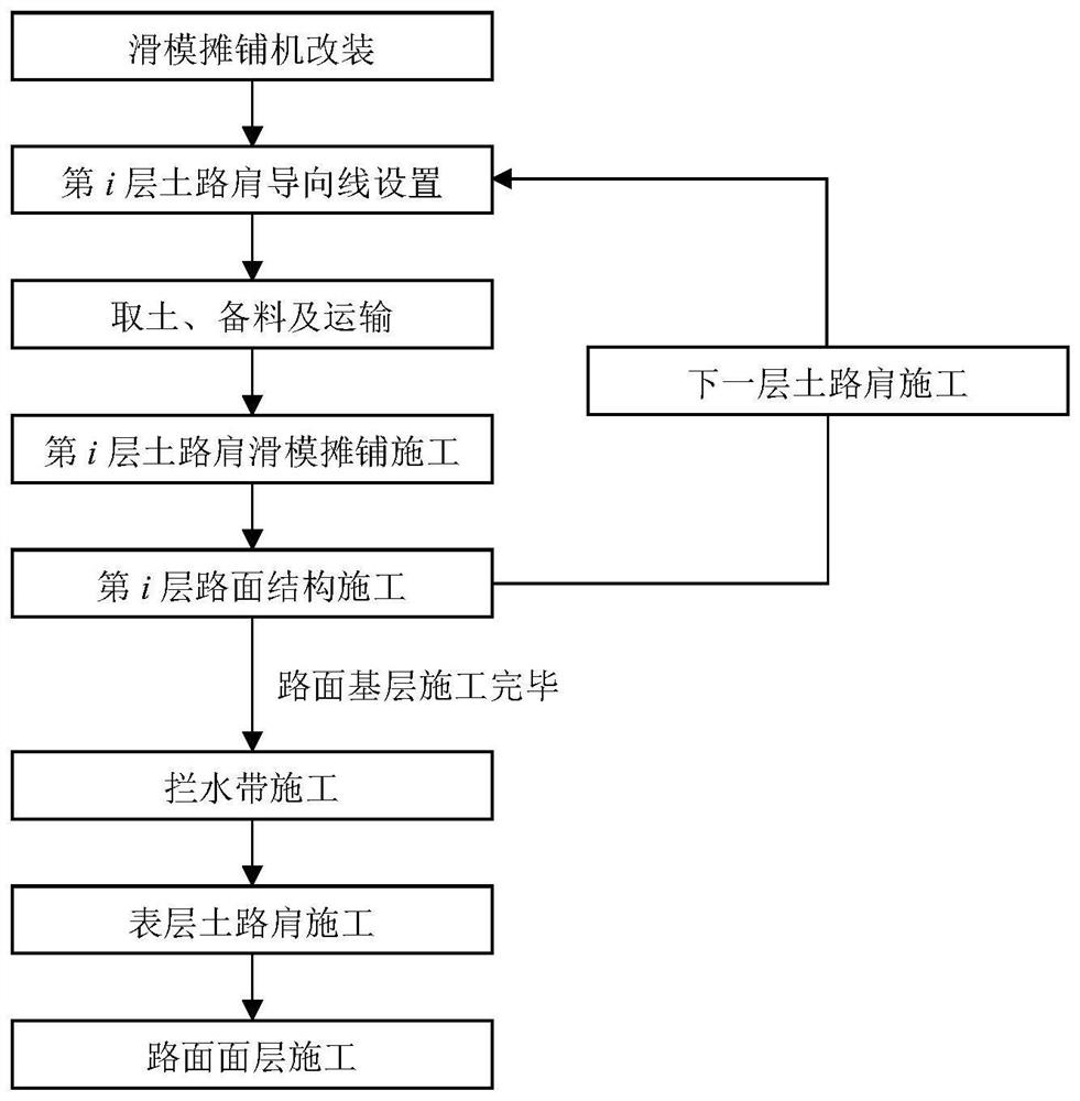
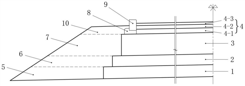
[0004] However, the existing soil road shoulder slipform paving construction method adopts one-time paving and molding, and the overall compactness of the soil road shoulder and the long-term stability of the slope need to be improved; , it is necessary to set additional side forms for the pavement structure layer, and formwork support and formwork removal are required to affect the construction progress
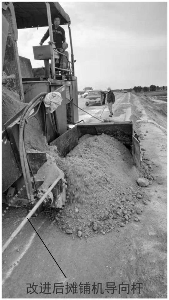
In addition, the guide rods of the existing slipform paver equipment are arranged horizontally, and centering hammers are installed at the ends to control the driving direction; Avoid shaking, and due to the change of the operator's perspective, it is easy to cause a deviation in the driving direction, which will eventually lead to poor construction quality of the soil shoulder

Method used


Image

  • Layered slip form paving construction method for earth shoulder of road
  • Layered slip form paving construction method for earth shoulder of road
  • Layered slip form paving construction method for earth shoulder of road

Examples


Embodiment Construction

[0028] In order to facilitate the understanding of the present invention, the present invention will be described more fully and in detail below in conjunction with the accompanying drawings and preferred embodiments, but the protection scope of the present invention is not limited to the following specific embodiments. It should be noted that, in the case of no conflict, the embodiments of the present invention and the features in the embodiments can be combined with each other.

[0029] Unless otherwise defined, all technical terms used hereinafter have the same meanings as commonly understood by those skilled in the art. "First", "second" and similar words used in the patent application specification and claims of the present invention do not indicate any order, quantity or importance, but are only for the convenience of distinguishing corresponding components. Likewise, words like "a" or "one" do not indicate a limitation of quantity, but indicate that there is at least on...


PUM


Abstract

A disclosed layered slip-form paving construction method for an earth shoulder of a road comprises the following steps: a first earth shoulder layer is constructed on the top surface of a roadbed by adopting slip-form paving, and a pavement cushion layer is constructed by taking the first earth shoulder layer as a side form; a second earth shoulder layer is constructed on the first earth shoulder layer and the pavement cushion layer in a slip form paving mode, and a pavement subbase layer is constructed on the pavement cushion layer with the second earth shoulder layer as a side form; a third earth shoulder layer is constructed on the second earth shoulder layer and the pavement subbase layer in a slip form paving mode, and the pavement base layer is constructed on the pavement subbase layer with the third earth shoulder layer as a side form; and a water retaining belt base and a water retaining belt are constructed on the pavement base layer, a fourth earth shoulder layer is constructed in the outer sides of the water retaining belt base and the water retaining belt in a hilling manner, and a pavement surface layer is constructed on the pavement base layer by taking the water retaining belt base, the water retaining belt and the fourth earth shoulder layer as side molds. The soil shoulder constructed through the layered slip form paving construction method is good in overall compactness, the long-term stability of a side slope is good, a side form does not need to be arranged during pavement structure layer construction, and the construction progress is accelerated.

Description

technical field [0001] The invention relates to the technical field of highway engineering construction, in particular to a layered sliding form paving construction method for road soil shoulders. Background technique [0002] The dirt shoulder is the band from the outer edge of the carriageway to the edge of the road, which provides lateral protection for the pavement structure. In traditional highway engineering construction, soil road shoulders are generally filled by manual earthing. First, support the side formwork, construct the pavement structure layer, and after the pavement base layer is constructed, the soil road shoulder is constructed by artificial earthing. This method requires a lot of manpower and high cost; compared with the mechanized construction of the pavement structure layer, it is slow and inefficient, which often restricts the overall progress of road construction; the uneven paving of soil materials and poor formation make it difficult to meet the sp...

Claims


Application Information

Patent Timeline
IPC IPC(8): E01C19/48
CPCE01C19/4886
Inventor 殷维国张华伍彦斌邹小文苏桂杰
Owner CHINA RAILWAY NO 5 ENG GRP
Learn More