Electric drill equipment capable of automatically adjusting speed according to hardness

An automatic speed regulation and electric drill technology, applied in metal processing equipment, driving devices, metal processing mechanical parts, etc., can solve the problems of difficult transmission, hard objects, difficult to drill, waste of time, etc., to achieve stable adjustment effect and prevent jamming , the effect of accurate rotation speed

Inactive Publication Date: 2021-06-29
曹县法恩亚家具有限公司
View PDF0 Cites 2 Cited by
  • Summary
  • Abstract
  • Description
  • Claims
  • Application Information

AI Technical Summary

Problems solved by technology

[0002] An electric drill is a drilling tool that uses electricity as power. It is the most demanded electric tool product. When using an electric drill, it often encounters the problem that the object is hard and difficult to drill. At this time, it is usually necessary to adjust the speed of the drill bit. This often It is necessary to pause the drilling work to adjust, and when the hardness of the object is difficult to determine, it needs to be adjusted repeatedly, which greatly wastes time. Some existing belt-driven electric drilling equipment is difficult to drive more stably. And generally do not have the function of anti-jamming, a kind of electric drill equipment with automatic speed regulation according to the hardness explained in the present invention can solve the above problems

Method used


Image

  • Electric drill equipment capable of automatically adjusting speed according to hardness
  • Electric drill equipment capable of automatically adjusting speed according to hardness
  • Electric drill equipment capable of automatically adjusting speed according to hardness

Examples


Embodiment Construction

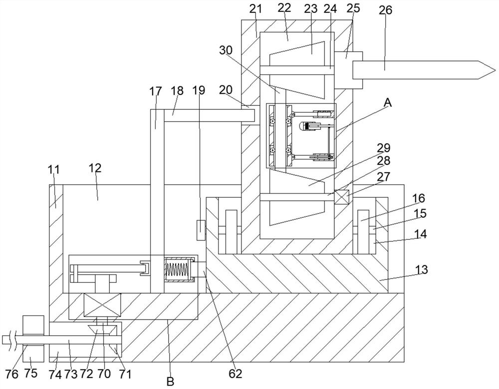
[0017] Combine below Figure 1-3 The present invention is described in detail, wherein, for the convenience of description, the orientations mentioned below are defined as follows: figure 1 The up, down, left, right, front and back directions of the projection relationship itself are the same.

[0018] An electric drill device with automatic speed regulation according to hardness according to the present invention includes a moving box 11, which is provided with a reciprocating push cavity 12 with an opening upward and to the right, and the lower wall of the reciprocating cavity 12 is left and right A clamping box 13 is slidably connected, and the lower wall of the reciprocating push chamber 12 is slidably connected with a hinge plate 17 on the left side of the clamp box 13, and the lower wall of the reciprocating push chamber 12 is rotatably connected with a hinge plate 17 located on the left side of the clamp box 13. 17, the crank shaft 58 on the left side, the right end su...


PUM


Abstract

The invention discloses electric drill equipment capable of automatically adjusting the speed according to the hardness. The electric drill equipment comprises a moving box, a reciprocating pushing cavity with an upward opening and a rightward opening is formed in the moving box, a clamping box is slidably connected to the lower wall of the reciprocating pushing cavity left and right, and a hinged plate located on the left side of the clamping box is slidably connected to the lower wall of the reciprocating pushing cavity left and right; and the lower wall of the reciprocating pushing cavity is rotationally connected with a crankshaft located on the left side of the hinged plate, a spring block is fixedly connected to the right end face of the hinged plate, a spring cavity is formed in the spring block, the right wall of the spring cavity communicates with a sliding cavity with a rightward opening, a clamping cavity with an upward opening is formed in the clamping box, and the left wall and the right wall of the clamping cavity are rotatably connected with a two-way screw. According to the electric drill equipment capable of automatically adjusting the speed according to the hardness, a drill bit can be driven to perform left-right reciprocating motion while being fed towards one side at a constant speed, so that the drill bit is prevented from being clamped, and meanwhile, the movement of a push block is controlled through the compression state of a spring.

Description

technical field [0001] The invention relates to the related fields of electric drills, in particular to an electric drill equipment with automatic speed regulation according to hardness. Background technique [0002] An electric drill is a drilling tool that uses electricity as power. It is the most demanded electric tool product. When using an electric drill, it often encounters the problem that the object is hard and difficult to drill. At this time, it is usually necessary to adjust the speed of the drill bit. This often It is necessary to pause the drilling work to adjust, and when the hardness of the object is difficult to determine, it needs to be adjusted repeatedly, which greatly wastes time. Some existing belt-driven electric drilling equipment is difficult to drive more stably. And it generally does not have the function of anti-jamming. The electric drill equipment with automatic speed regulation according to the hardness explained in the present invention can sol...

Claims


Application Information

Patent Timeline
Patent Type & Authority Applications(China)
IPC IPC(8): B23Q5/04B23Q5/22B23Q5/28
CPCB23Q5/04B23Q5/22B23Q5/28
Inventor 高远
Owner 曹县法恩亚家具有限公司
Why Eureka
Try Eureka