Pin forming tool for chip manufacturing

A technology for forming tooling and chips, which is applied in the field of chip manufacturing, can solve problems such as complicated and troublesome operation, bending and breaking of pins, and poor bending consistency, so as to reduce welding quality problems, prevent re-bending, and achieve high consistency Effect

Inactive Publication Date: 2021-06-29
南京浦梵贸易有限公司
View PDF0 Cites 0 Cited by
  • Summary
  • Abstract
  • Description
  • Claims
  • Application Information

AI Technical Summary

Problems solved by technology

[0003] The bending of the chip pins includes two bending points, the upper and lower, and the two bending points are right-angled structures. Manual bending results in poor bending consistency, which is easy to cause the pins to bend and break, and soldering to the circuit board will also cause The welding is not firm and affects the welding quality. After the chip pins are bent and formed, they are generally taken out of the tooling manually, but the chip is small in size and difficult to take. The operation process is complicated and troublesome. Therefore, those skilled in the art provide a Lead Forming Tooling for Chip Manufacturing to Solve the Problems Raised in the Background Art Above

Method used


Image

  • Pin forming tool for chip manufacturing
  • Pin forming tool for chip manufacturing
  • Pin forming tool for chip manufacturing

Examples


Embodiment Construction

[0021] The following will clearly and completely describe the technical solutions in the embodiments of the present invention with reference to the accompanying drawings in the embodiments of the present invention. Obviously, the described embodiments are only some, not all, embodiments of the present invention. Based on the embodiments of the present invention, all other embodiments obtained by persons of ordinary skill in the art without making creative efforts belong to the protection scope of the present invention.

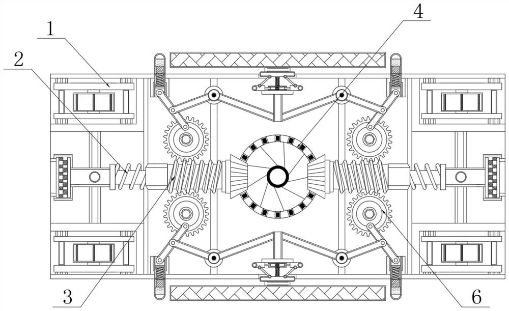
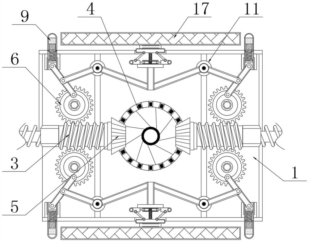
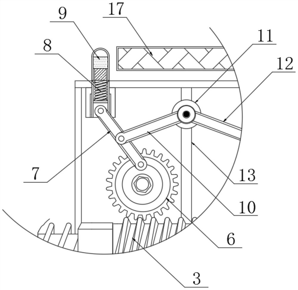
[0022] see Figure 1-6 , a lead forming tool for chip manufacturing, including a fixed frame 1, the interior of the fixed frame 1 is fixedly connected with a limit spring 2, and one end of the limit spring 2 is movably connected with a threaded rod 3, and the steps of the threaded rod 3 are fixed The bevel gear 5 is connected, and the back surface of the bevel gear 5 is meshed with the tooth disc 4, which is movably connected to the inside of the fixed frame 1...


PUM


Abstract

The invention relates to the technical field of chip manufacturing, in particular to a pin forming tool for chip manufacturing. Limiting springs are fixedly connected in fixing frames, one ends of the limiting springs are movably connected with threaded rods, bevel gears are fixedly connected to ladder sections of the threaded rods, the rear surfaces of the bevel gears are meshed with a fluted disc, the two sides of the threaded rod are both engaged with gears, first connecting rods are movably connected to the outer surfaces of the gears, first springs are fixedly connected to one ends of the first connecting rods, ejector rods are fixedly connected to one ends of the first springs, limiting rods are fixedly connected to the inner walls of the fixing frames, rotating discs are movably connected to the outer surfaces of the limiting rods, and second connecting rods are fixedly connected to one sides of the outer surfaces of the rotating discs. A chip pin can be bent in the upward moving process of the ejector rods, so that manual work is replaced, the bending strength is controlled more accurately, the consistency of formed chip pin forming is high, and firmness during welding is facilitated.

Description

technical field [0001] The invention relates to the technical field of chip manufacturing, in particular to a lead forming tool for chip manufacturing. Background technique [0002] The chip is the tube name of the semiconductor component product, and it is the carrier of the integrated circuit. In order to extend downward perpendicular to the chip, the outer pins of the chip are properly bent according to the needs of use, so as to facilitate welding and fixing. [0003] The bending of the chip pins includes two bending points, the upper and lower, and the two bending points are right-angled structures. Manual bending results in poor bending shape consistency, which is easy to cause the pins to bend and break, and soldering to the circuit board will also cause The welding is not firm and affects the welding quality. After the chip pins are bent and formed, they are generally taken out of the tooling manually, but the chip is small in size and difficult to take. The operati...

Claims


Application Information

Patent Timeline
Patent Type & Authority Applications(China)
IPC IPC(8): B21F1/00
CPCB21F1/00
Inventor 张锡慧
Owner 南京浦梵贸易有限公司
Why Eureka
Try Eureka