Hydraulic lock loading test device

A testing device and hydraulic loading technology, applied in the direction of fluid pressure actuation device, fluid pressure actuation system test, fluid pressure actuation system components, etc., can solve the problem of inability to effectively detect the actual performance and comprehensive characteristics of hydraulic locks, and mutual influence , Affect the safety of the hydraulic lock control system and other issues

Pending Publication Date: 2021-06-25
SICHUAN LINGFENG AVIATION HYDRAULIC MACHINERY
View PDF0 Cites 0 Cited by
  • Summary
  • Abstract
  • Description
  • Claims
  • Application Information

AI Technical Summary

Problems solved by technology

During the unlocking process, the hydraulic lock is released with the load of the cabin door after the hydraulic reversing, and there are problems of mutual control and mutual influence among the control actions.
During the assembly and commissioning stage, because the hydraulic lock carries the parts loaded by the cabin door and the hydraulic lock control system cannot be installed on the cabin door to simulate the actual working conditions for testing, the quality of the hydraulic lock cannot be inspected and guaranteed, and the probability of repairs reaches 40%. %
The pressure and flow of the existing power source are large, the pressure of the hydraulic lock system will fluctuate with the resistance of the loading test, the working conditions are complicated, the pressure of the loading system is abnormal, and after the fluid medium is used repeatedly, the indicators such as viscosity and pH value will deteriorate Phenomenon; if there is leakage during the test, the pressure of the hydraulic lock system will be insufficient, which is very different from the actual working conditions
Traditional hydraulic loading equipment uses multiple sets of throttling nozzles to switch to achieve flow control. In the debugging stage, it is necessary to obtain the flow characteristics of throttling nozzles with different diameters under working pressure through experiments; A lot of time and a lot of preparation work before the manual test can not effectively detect the actual performance and comprehensive characteristics of the hydraulic lock with the door load system parts after maintenance, which affects the final use safety of the hydraulic lock control system

Method used


Image

  • Hydraulic lock loading test device
  • Hydraulic lock loading test device

Examples


Embodiment Construction

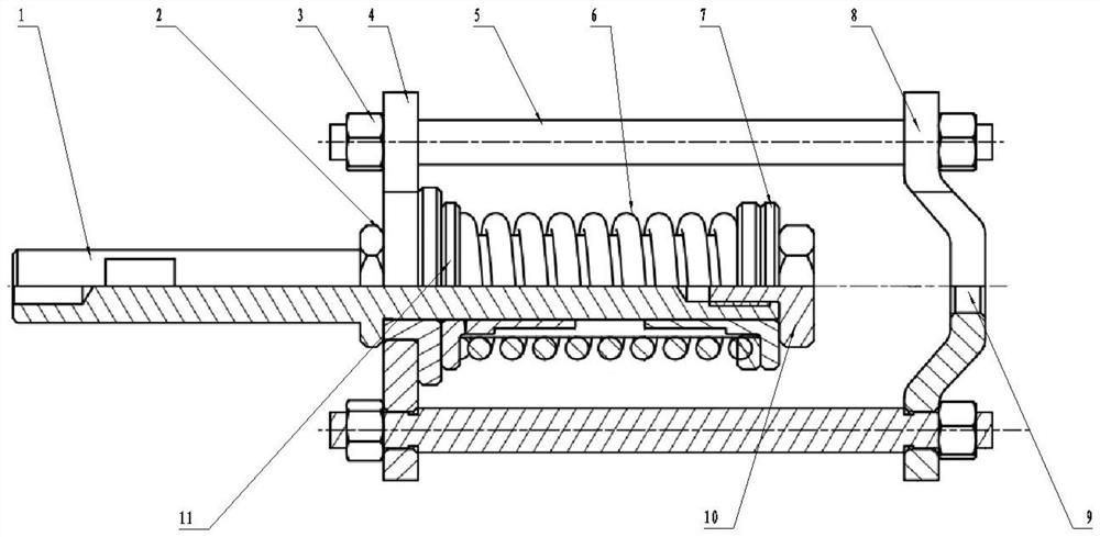
[0013] refer to figure 1 , figure 2 . In the preferred example described below, a hydraulic lock loading test device includes: a transmission link 1 that is coupled and connected to the hydraulic lock 12 at one end, and a loading cylinder connecting plate 8 that is connected to a hydraulic loading cylinder, wherein: the loading cylinder is connected The plate 8 adopts a bow-shaped connecting plate, and connects with the hydraulic loading cylinder through the loading cylinder connecting hole on the bow-shaped connecting plate. The loading cylinder connecting plate 8 connects the spring seat plate 4 through the circumferential loading connecting rod 5, and the loading connecting rod 5 passes through the back tightening nut 3 Carry out solid connection assembly, pre-installed with the spring guide sleeve 11, the opposite end spring guide sleeve 7 and the transmission link 1 of the loading spring 6 through the center hole of the spring seat plate 4, the spring guide sleeve 11 at...


PUM


Abstract

The invention discloses a hydraulic lock loading test device which is adjustable in loading force and controllable in loading speed and loading force. According to the technical scheme, a loading cylinder connecting plate is communicated with a hydraulic loading cylinder through a loading cylinder connecting hole in an arch-shaped connecting plate and is connected with a spring seat plate through a circumferential loading connecting rod, a transmission connecting rod preassembled with a spring guide sleeve, an opposite-end spring guide sleeve and a loading spring passes through a spring seat plate center hole, and after the spring guide sleeve and the opposite-end spring guide sleeve at the two ends of the loading spring are tightened back to back through a limiting nut and an adjusting nut to form a spring reversing mechanism, the loading spring assembled on the transmission connecting rod 1 is axially guided, and a quick reversing loading mechanism for simulating cabin door movement is formed, and the quick reversing loading mechanism divides the loading process into two parts of simulating and detecting normal locking and on-load unlocking, detects displacement and loading force indexes in the movement process, and effectively examines a detected hydraulic lock.

Description

technical field [0001] The invention relates to a hydraulic lock loading test mechanism capable of realizing instantaneous reversing through the loading test of the hydraulic lock in the motion test process during the hydraulic lock test process. Background technique [0002] The hydraulic lock is a hydraulic actuator that converts hydraulic energy into mechanical energy. In the aircraft hydraulic system, the aircraft door is locked after closing, and the hydraulic lock release mechanism is activated before the door is opened to realize the normal closing and release of the door. After the other actuators drive the door to the closed state during the flight of the aircraft, a stable hydraulic lock mechanism is required to lock and maintain it to ensure the state of the door during the flight. After receiving the command signal to open the hatch, the hydraulic lock can be released in time through the hydraulic system to ensure the normal opening of the hatch. The performance...

Claims


Application Information

Patent Timeline
Patent Type & Authority Applications(China)
IPC IPC(8): F15B19/00F15B21/00
CPCF15B19/00F15B21/00
Inventor 陈光浩贺超江枫褚文洋万兴灵
Owner SICHUAN LINGFENG AVIATION HYDRAULIC MACHINERY
Why Eureka
Try Eureka