
Annular vibration reduction axle box with temperature measuring hole

A technology of damping shafts and temperature measuring holes, which is applied to axle boxes, railway vehicle shape measuring devices, railway car body parts, etc., can solve the problems of complex manufacturing process, high manufacturing and maintenance costs, flying sand and gravel impact, etc. Achieve the effects of improving the strength of the mechanical structure, reducing the shape and size, and ensuring the vibration reduction index

Pending Publication Date: 2021-06-25
CRRC CHANGCHUN RAILWAY VEHICLES CO LTD
View PDF0 Cites 0 Cited by
  • Summary
  • Abstract
  • Description
  • Claims
  • Application Information

AI Technical Summary

Problems solved by technology

[0003] In order to solve the problem existing in the existing wheel-to-external axle box, the overall axial width of the wheel-set has been greatly increased, which is not only more likely to be hit by flying sand and gravel along the railway, but also increases the overall radius of gyration of the bogie, which is not conducive to the minimum train The improvement of the curvature of the curve; and the technical problems of the isosceles trapezoidal axle box built-in primary suspension structure with double-sided rubber stacks, complex manufacturing process, cumbersome disassembly and maintenance procedures, and high manufacturing and maintenance costs. Provide a ring-shaped damping axle box with a temperature measuring hole

Method used


Image

  • Annular vibration reduction axle box with temperature measuring hole
  • Annular vibration reduction axle box with temperature measuring hole
  • Annular vibration reduction axle box with temperature measuring hole

Examples


Embodiment Construction

[0018] The present invention will be described in further detail below in conjunction with the accompanying drawings.

[0019] Such as Figure 4 to Figure 9 As shown, the annular damping axlebox with temperature measuring holes of the present invention includes axle bearing B-2, axlebox positioning and temperature measuring heat conduction sheath B-3 and vibration damping rubber ring B-1, axlebox positioning and measuring The temperature and heat conduction sheath B-3 is coaxially fixed with the outer ring of the axle bearing B-2, and the inner ring of the axle bearing B-2 is coaxially press-fitted and fixedly connected to both ends of the axle d. The axle box positioning and temperature measurement and heat conduction protection The upper part of the sleeve B-3 and the damping rubber ring B-1 is provided with a socket for positioning the temperature sensor G.

[0020] Axis box positioning and temperature measurement and heat conduction sheath B-3 shell socket B-3-1 and rubbe...


PUM


Abstract

An annular vibration reduction axle box with a temperature measurement hole belongs to the field of axle box devices of bogies of railway vehicles and comprises an axle bearing, an axle box positioning and temperature measurement heat conduction sheath and a vibration reduction rubber ring, the axle box positioning and temperature measurement heat conduction sheath is coaxially and fixedly connected with an outer ring of the axle bearing, the inner ring of the axle bearing is coaxially pressed and fixedly connected to the axle and the upper part of the damping rubber ring, and the central connecting line of a shell socket for positioning the temperature sensor and a rubber ring blind hole socket of the damping rubber ring forms an angle of 60 degrees relative to the horizontal plane. The axle box is internally arranged in the inner sides of the wheel sets, so that the damage risk caused when the axle box is externally arranged is reduced, the overall structural size and the turning radius of the bogie are effectively reduced, and the curve passing capacity of the bogie is further improved; and according to the annular vibration reduction axle box, the semi-annular shell and the semi-annular clamp type axle box hanging base are buckled into a complete circular ring structure in a bolt connection split type clamp mode, installation, disassembly and maintenance are convenient, and meanwhile the adverse effect of welding deformation is avoided.

Description

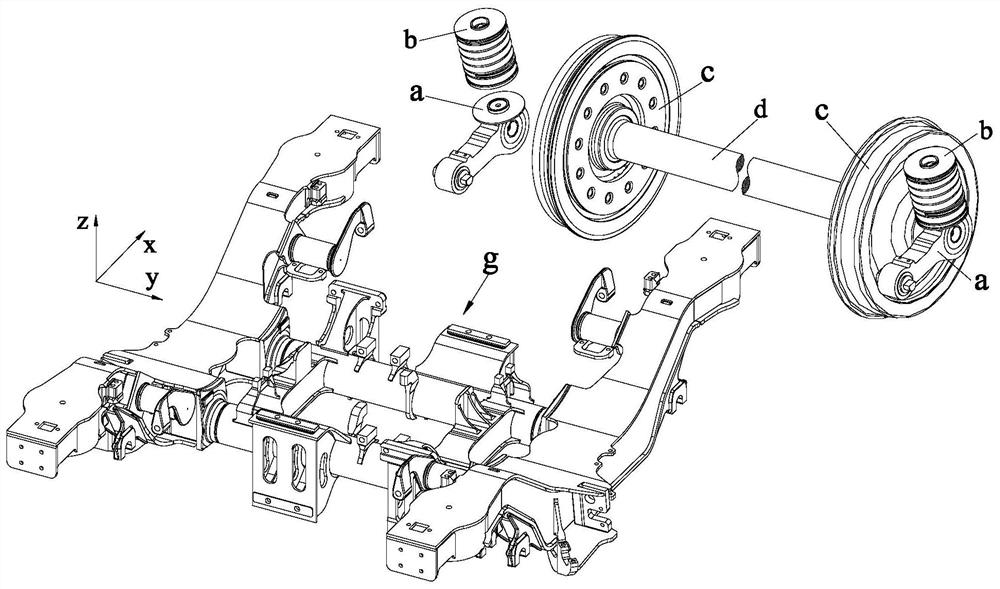
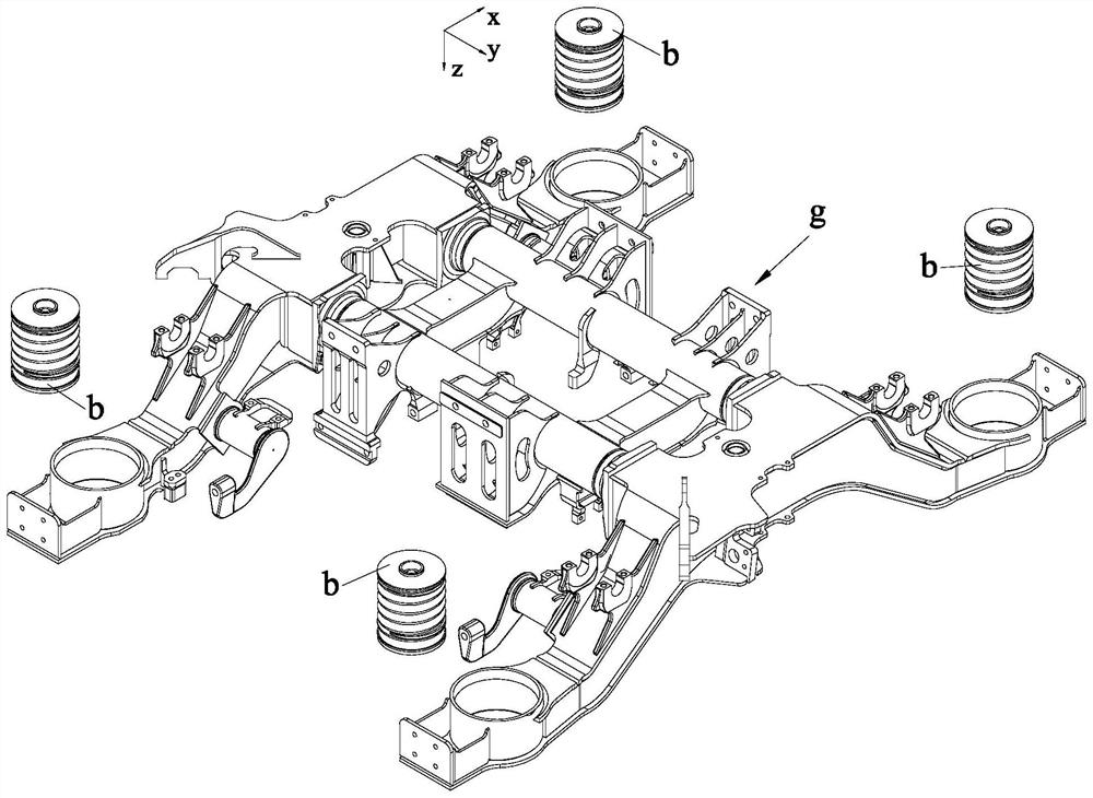
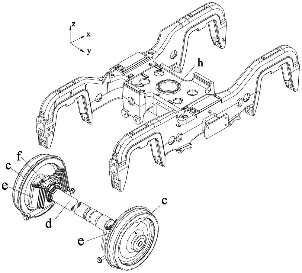
technical field [0001] The invention belongs to the field of rail vehicle bogie axle box devices, and in particular relates to an annular damping axle box with a temperature measuring hole. Background technique [0002] Such as Figure 1 to Figure 3 As shown, the frame of the rail passenger car bogie can be divided into a welded frame g formed by butt-welding of multiple plates and a cast frame h formed by integral casting. The primary suspension device of the bogie is used to lower the wheel rail and bump vibrations generated by the axle, such as figure 1 and figure 2 As shown, the old typical primary suspension device is composed of a tray-type axle box a and a series of steel springs b installed on the tray-type axle box a. The upper end of the primary steel spring b is used to support the end of the side beam of the bogie round cap. Because this typical primary suspension device is installed on the end of the axle d outside the wheel c, it is called an external axle...

Claims


Application Information

Patent Timeline
IPC IPC(8): B61F15/20B61K9/06
CPCB61F15/20B61K9/06
Inventor 李涛阴晓铭何龙王云鹏
Owner CRRC CHANGCHUN RAILWAY VEHICLES CO LTD
Learn More