
Medical pipe machining device and machining method thereof

A processing device and medical tube technology, applied in the field of tube processing, to achieve rapid and uniform arcing and avoid damage

Inactive Publication Date: 2021-06-25
张香连
View PDF1 Cites 1 Cited by
  • Summary
  • Abstract
  • Description
  • Claims
  • Application Information

AI Technical Summary

Problems solved by technology

However, the device cannot automatically and quickly perform rapid and uniform arcing of medical plastic tubes

Method used


Image

  • Medical pipe machining device and machining method thereof
  • Medical pipe machining device and machining method thereof
  • Medical pipe machining device and machining method thereof

Examples


specific Embodiment approach 1

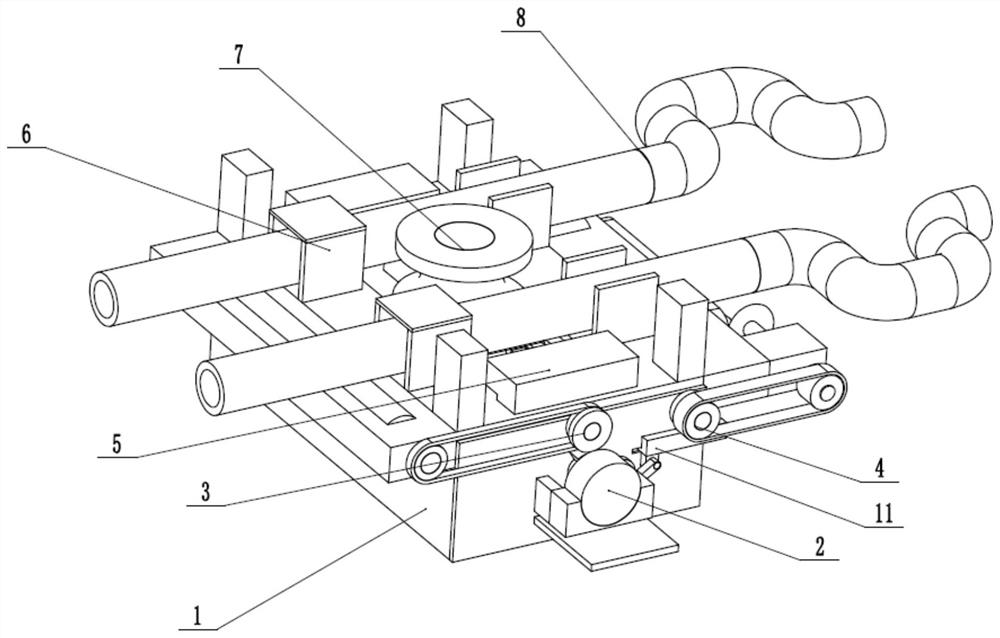
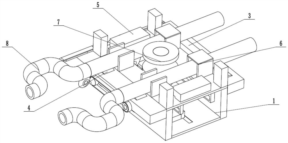
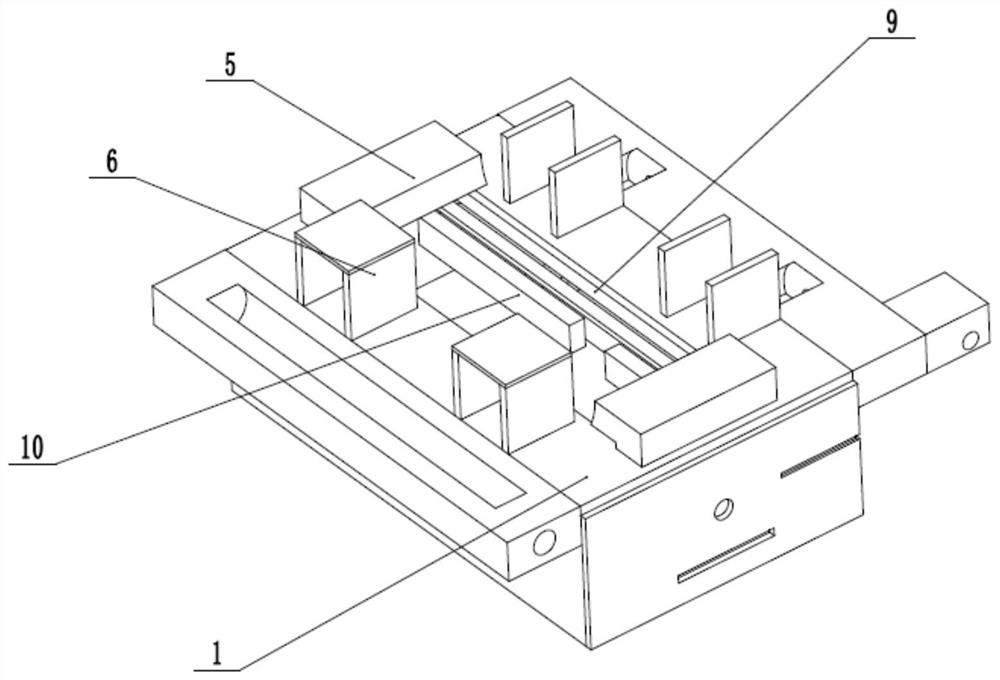
[0030] Such as Figure 1 to Figure 8 As shown, a medical tube processing device includes a tube arc processing frame 1, a combined driver 2, an intermittent drive adder 3, an intermittent drive steering gear 4, two arc-shaped top seats 5, four limit frames 6, an arc Extruder 7, two adding pipes 8 and reciprocating drive diverter 11, the combined driver 2 is rotatably connected on the pipe arc processing frame 1, the combined driver 2 intermittently drives the intermittent drive adder 3 and the reciprocating drive variable The reciprocator 11, the intermittent drive adder 3 and the intermittent drive diverter 4 are respectively rotatably connected to the two ends of the pipe arc processing frame 1, the reciprocating drive diverter 11 intermittently drives the intermittent drive diverter 4 to reciprocate, and the two arc tops Seat 5 is uniformly and fixedly connected to pipe arc processing frame 1, and four limit frames 6 are evenly and fixedly connected to pipe arc processing f...

specific Embodiment approach 2

[0032] Such as Figure 1 to Figure 8 As shown, this embodiment further explains the first embodiment, the pipe arc processing frame 1 is provided with a central slot, the pipe arc processing frame 1 is fixedly connected to the slide rail 9, and the two fixed racks 10 are fixedly connected In the pipe arc processing frame 1.

specific Embodiment approach 3

[0034] Such as Figure 1 to Figure 8 As shown, this embodiment further explains the second embodiment. The combined driver 2 is fixedly connected to the pipe arc processing frame 1 through a point-release fixing seat, and the transmission shaft of the combined driver 2 is connected to the pipe arc processing frame in rotation. 1, the transmission shaft of the combination driver 2 is fixedly connected with an intermittent drive gear 12, and the intermittent drive gear 12 is intermittently meshed to drive the intermittent drive adder 3 and the reciprocating drive commutator 11. Combined driver 2 is connected to electricity and drives intermittent drive adder 3 and add rubber roller 13 to rotate by connecting intermittent drive gear 12, adding pipe 8 evenly in pipe arc processing frame 1, and then stops.


PUM


Abstract

The invention relates to the field of pipe machining, in particular to a medical pipe machining device and a machining method thereof. The machining method comprises the following steps that adding pipes needing to be subjected to continuous arc bending are heated through a limiting frame to be added; a combined driver intermittently drives an intermittent driving adder to intermittently add the adding pipes through the adding rubber rollers and then stops; the combined driver drives a pressurizing intermittent driving gear, a sliding gear ring plate and a lower sliding base, so that an arc-shaped extruder extrudes the heated and softened adding pipes onto an arc-shaped top base; meanwhile, the arc-shaped extruder stably drives the adding pipes in an extruding process through meshing of a fixing gear and a fixing rack, and damage caused by excessive extruding is avoided; after being extruded into an arc shape, the combined driver intermittently drives a reciprocating driving direction changing device to drive an intermittent driving steering gear to rotate so as to convey out the adding pipes at the arc-shaped part, and interference is avoided; and the process is repeated.

Description

technical field [0001] The invention relates to the pipe processing field, and more specifically relates to a medical pipe processing device and a processing method thereof. Background technique [0002] The patent number is CN201920426945.8, which discloses a device for medical pipe welding, including a box body, a welded pipe is placed inside the support tube body, and gears are fixedly installed on the side of the top of the box body, and the gear passes through the outer wall of the support tube body There is a gear bar meshed with the support pipe body, the inside of the chute is slidingly connected with a vertical rod, the top of the bottom plate is fixedly installed with a spring, and the top of the spring is fixedly connected with the other side of the bottom end of the welding head, and the side of the welding head passes through The second rotating shaft is movably connected with the bottom end of the pull rod. This invention is a device for welding medical pipes. ...

Claims


Application Information

Patent Timeline
Patent Type & Authority Applications(China)
IPC IPC(8): B29C53/08
CPCB29C53/083
Inventor 张香连
Owner 张香连
Learn More