
Motor and gearbox assembling equipment and operation method thereof

A technology for assembling equipment and tooth boxes, which is applied in the direction of metal processing equipment, metal processing, manufacturing tools, etc., can solve the problems of low degree of automation, waste of labor, and low efficiency, and achieve compact structure, high efficiency, and reduced manual labor. Effect

Pending Publication Date: 2021-06-25
深圳市合利士智能装备有限公司
View PDF1 Cites 2 Cited by
  • Summary
  • Abstract
  • Description
  • Claims
  • Application Information

AI Technical Summary

Problems solved by technology

[0004] The above-mentioned patents have the advantages of ensuring that the sensor magnetic sheet can be installed at a suitable height and the precise positioning between the sensor magnetic sheet and the circuit board, but it also has defects, such as: its degree of automation is low, manual assistance is required, and labor is wasted , artificial production results in low efficiency and poor precision

Method used


Image

  • Motor and gearbox assembling equipment and operation method thereof
  • Motor and gearbox assembling equipment and operation method thereof
  • Motor and gearbox assembling equipment and operation method thereof

Examples


Embodiment 1

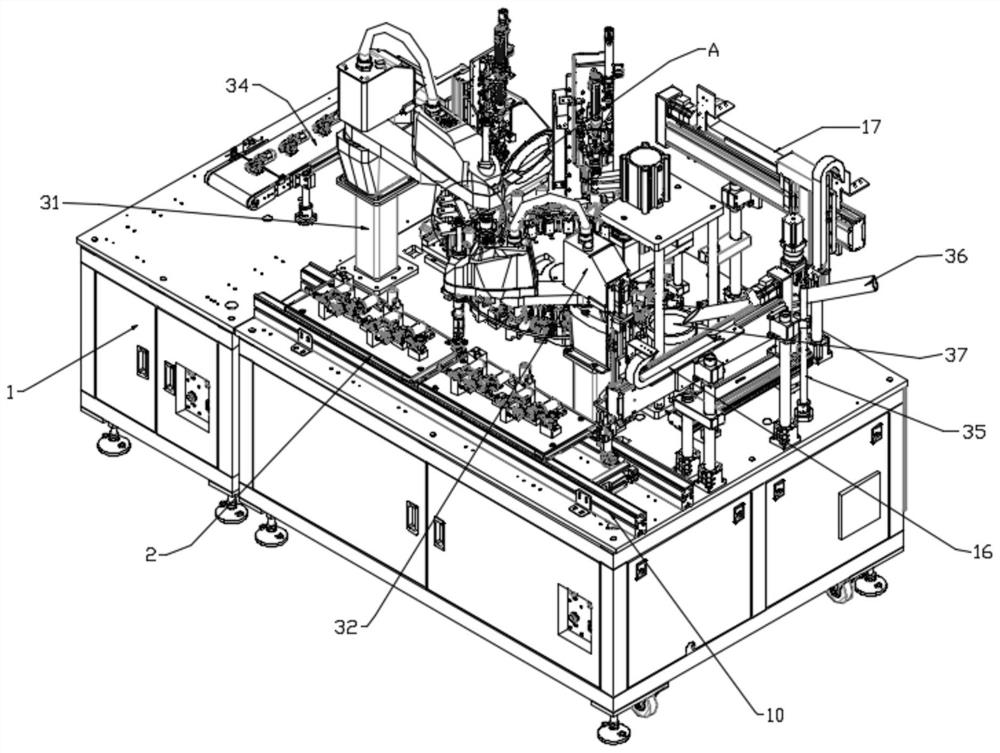
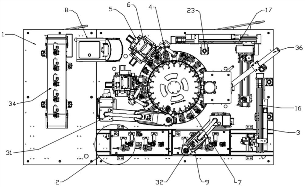
[0047] Motor and tooth box assembly equipment, including operating table 1,

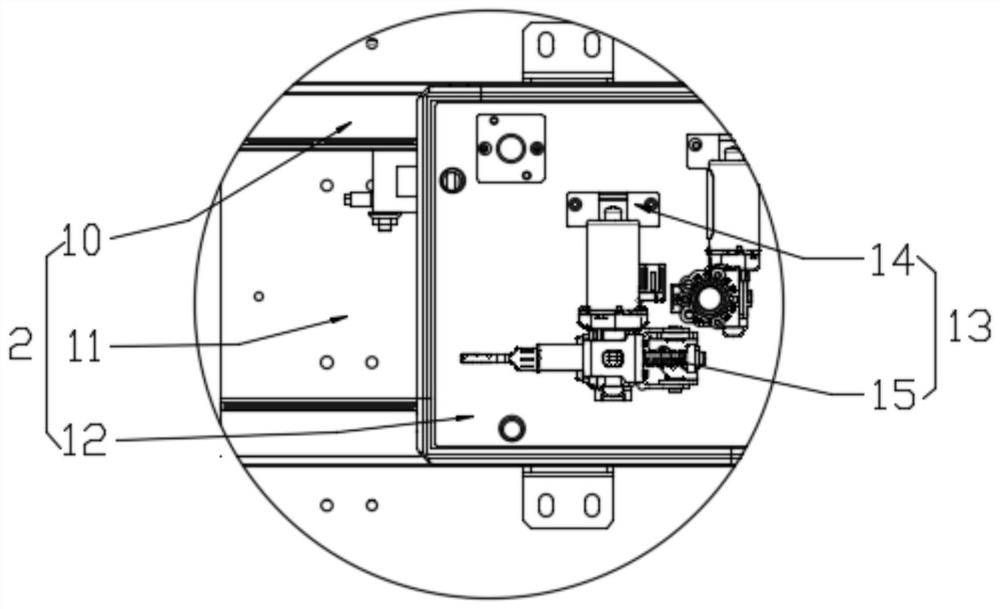
[0048] The top of the console 1 is provided with a conveying mechanism 2 for conveying dental boxes;

[0049] The material shifting mechanism 3 used for conveying the motor, the material moving mechanism 3 is located on one side of the conveying mechanism 2;

[0050] It is used to press the motor transferred by the material transfer mechanism 3 into the press-fit mechanism 4 in the tooth box, and the press-fit mechanism 4 is arranged on one side of the material transfer mechanism 3;

[0051] An assembly mechanism 5 for assembling the tooth box and the motor, the assembly mechanism 5 includes two multi-degree-of-freedom screw machines 6 installed on the top of the console 1;

[0052] A rotating mechanism 7 for placing the motor and the tooth box to be assembled in the assembly mechanism 5, and the rotating mechanism 7 is arranged at the center of the console 1;

[0053]A detection mechanism 8 for de...

Embodiment 2

[0074] The present invention also provides an operation method for the motor and tooth box assembly equipment, which specifically includes the following steps:

[0075] Step 1: first place the dental box on the conveyor belt 11 on the front side of the console 1 for transportation, then use the second manipulator 32 to transfer the dental box to the assembly station 28 corresponding to the turntable 27, and then the turntable 27 rotates to place the tooth box The box is turned to the assembly position;

[0076] Step 2: Place the motor on the material transfer mechanism 3 on the side of the console 1, then transfer it to the assembly position in a right-angle turn, then insert the motor into the tooth box, turn the turntable 27 to turn the motor and the tooth box to screw position, and then through the press-fit mechanism 4 of the screw position, use the press-fit cylinder 25 and the pressure rod 26 to press the motor into the tooth box first, and then the multi-degree-of-freed...


PUM


Abstract

The invention discloses motor and gearbox assembling equipment and an operation method thereof. According to the technical scheme, the motor and gearbox assembling equipment is characterized by comprising an operation table provided with a conveying mechanism used for conveying a gearbox at the top; a material transferring mechanism used for conveying a motor and positioned on one side of the conveying mechanism; a press-fitting mechanism used for pressing the motor transferred by the material transferring mechanism into the gearbox and arranged on one side of the material transferring mechanism; an assembling mechanism used for assembling the gearbox and the motor and comprising two multi-degree-of-freedom screw machines mounted at the top of the operation table; and a rotating mechanism used for placing the to-be-assembled motor and the to-be-assembled gearbox in the assembling mechanism and arranged at the center of the operation table. Feeding, clamping, assembling, detecting and taking can be fully automatically carried out, manual participation is not needed, and the purposes that the whole process is fully automatically operated, the manual labor amount is reduced, and the production efficiency and the assembling precision are improved are achieved.

Description

technical field [0001] The invention belongs to the field of mechanical processing, and in particular relates to motor and tooth box assembly equipment and an operation method thereof. Background technique [0002] The motor is the electric motor, the engine. The working principle is to drive the starter rotor to rotate through the energized coil in the magnetic field, and the small gear on the rotor drives the engine flywheel to rotate; the tooth box is the gearbox. The speed and torque of rotation are increased or decreased through the meshing of gears of different sizes, also known as a gearbox. The large gear drives the small teeth to reduce the torque for speeding up, and the small gear drives the large teeth for deceleration to increase the torque; the motor and the gear box are assembled to form a motor power assembly. When assembling the motor and the gear box, assembly equipment is required. [0003] You can refer to the Chinese patent with publication number CN20...

Claims


Application Information

Patent Timeline
Patent Type & Authority Applications(China)
IPC IPC(8): B23P19/027B23P19/06
CPCB23P19/001B23P19/007B23P19/027B23P19/069
Inventor 汪飞周华国廖建勇
Owner 深圳市合利士智能装备有限公司
Learn More