
Position determination method, position determination device, and position determination system

A technique for determining a method and an approximate location, applied in transmission systems, location-based services, short-range communication services, etc.

Inactive Publication Date: 2021-06-22
ALPS ALPINE CO LTD
View PDF0 Cites 0 Cited by
  • Summary
  • Abstract
  • Description
  • Claims
  • Application Information

AI Technical Summary

Problems solved by technology

If the RSSI value attenuated by the influence of the human body is used as a normal value, no matter it is the position fingerprinting method or the triangulation method, there will be a large error

Method used


Image

  • Position determination method, position determination device, and position determination system
  • Position determination method, position determination device, and position determination system
  • Position determination method, position determination device, and position determination system

Examples


Embodiment 1

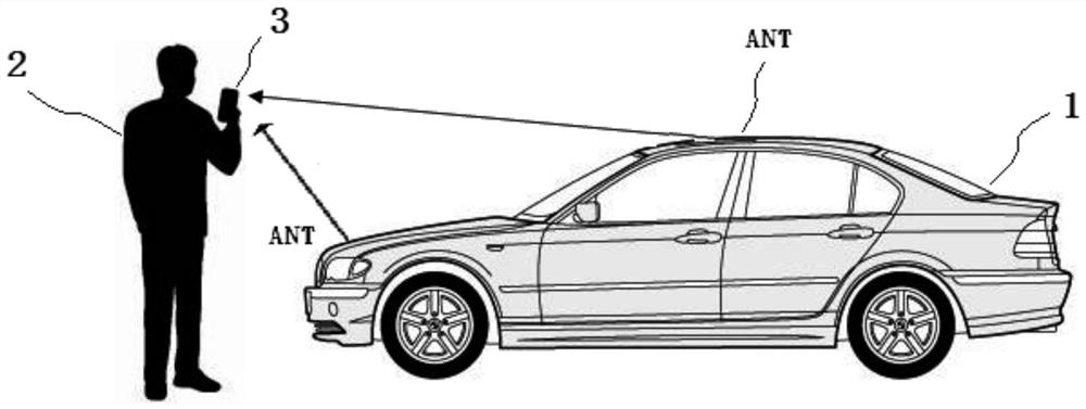
[0067] First, if Figure 4 As shown, at point a, the user 2 is far behind the right rear of the vehicle 1 .

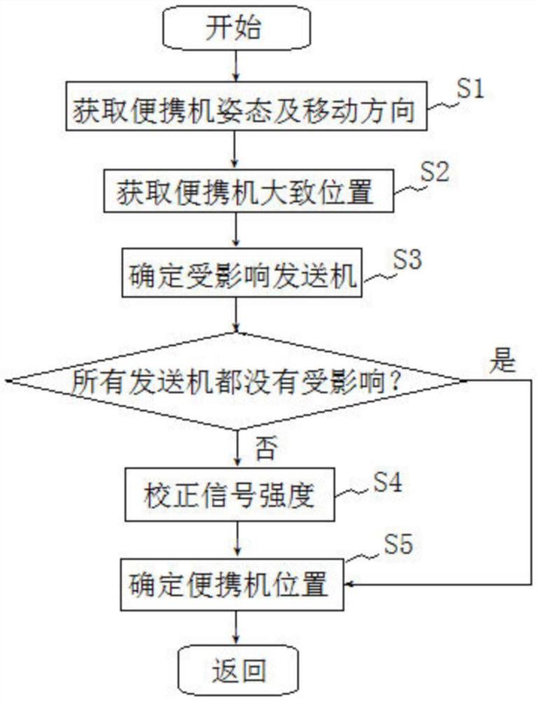
[0068] At this time, the portable device posture and moving direction acquisition unit 101 acquires the portable device posture as "put in the right pocket" and the moving direction of the user 2 as f1 according to a plurality of sensors built in the portable device 3 (S1).

[0069] Next, the approximate portable device position acquisition unit 102 acquires the approximate portable device position of the portable device 3 with respect to the vehicle 1 based on the signals received from the plurality of antennas ANT1 to ANT5 ( S2 ). Such as Figure 5 As shown, in the coordinates based on the vehicle 1 , the obtained approximate position of point a is (x, y). As mentioned above, the approximate position may deviate from the real position, but this has little impact on the accuracy of finally determining the position of the portable device, so it can be ignored.

[00...

Embodiment 2

[0076] When user 2 walks from point a to point b, such as Figure 4 As shown, at this time, the moving direction f2 of the user 2 and the direction F2 of the user 2 towards the vehicle 1 are still inconsistent, and their included angle is greater than the angle between the direction F1 and the moving direction f1 in Embodiment 1.

[0077] At this time, the posture and moving direction acquiring unit 101 of the portable device still acquires the posture of "put in the right pocket" and the moving direction f2 (S1).

[0078] Next, the approximate position acquiring unit 102 of the portable device acquires the approximate position (x', y') of the portable device 3 relative to the vehicle 1 based on the signals received from each antenna (S2, refer to Figure 6 ).

[0079] Next, in the step S3 of determining the affected transmitter, since the user 2 is relatively close to the vehicle 1 at this time, it is not appropriate to treat the vehicle as a point. Therefore, in this step, ...


PUM


Abstract

The invention provides a position determination method, a position determination device and a position determination system, which can reduce the influence of RSSI value attenuation caused by the human body and greatly improve the positioning accuracy. The position determination method comprises the following steps: a step of obtaining the posture and the moving direction of the portable computer; a portable device approximate position acquisition step of acquiring a portable device approximate position of the portable device with respect to the vehicle; an affected transmitter identification step of identifying, from among the plurality of transmitters, an affected transmitter in which there is a user between the affected transmitter and the portable device; a signal strength correction step of correcting the strength of a signal received by the portable device from the affected transmitter to the strength of a signal to be received from the transmitter when there is no user between the portable device and the transmitter; and a portable device position determination step of determining the position of the portable device with respect to the vehicle using the corrected signal intensity.

Description

technical field [0001] The present invention relates to a position specifying method, a position specifying device, and a position specifying system for specifying the position of a portable device relative to a vehicle based on received signal strength of a wireless signal transmitted from a vehicle transmitter in a keyless entry system or the like. Background technique [0002] Conventionally, there is known a keyless entry system that performs vehicle operations such as locking or unlocking doors of a vehicle and starting an engine based on wireless communication between a vehicle-side device and a portable device. Furthermore, there is also known a technology that uses positioning based on Bluetooth Low Energy (BLE) for indoor and automotive PEPS (Passive Entry Passive Start, keyless entry and start systems) positioning functions. In this technology, it is necessary to deploy two or more BLE modules at different fixed positions indoors and in cars (hereinafter also refer...

Claims


Application Information

Patent Timeline
Patent Type & Authority Applications(China)
IPC IPC(8): H04W64/00H04W4/02H04W4/80H04B17/318
CPCH04W4/02H04W4/027H04W64/00H04B17/318H04W4/80
Inventor 邱祖锋
Owner ALPS ALPINE CO LTD
Learn More