Transformer area reactive power compensation system and method
A compensation system, a technology in the station area, applied in reactive power compensation, reactive power adjustment/elimination/compensation, information technology support systems, etc., can solve the problems of insufficient compensation capacity, insufficient precision, overcompensation, etc., to achieve the maximum power factor , achieve precise control, and achieve the effect of regional voltage
- Summary
- Abstract
- Description
- Claims
- Application Information
AI Technical Summary
Problems solved by technology
Method used
Image


Examples
Embodiment 1
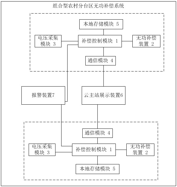
[0054] Such as figure 1 As shown, the present invention provides a reactive power compensation system in a station area, including a reactive power compensation device 2, a voltage acquisition module 3, a compensation control module 1, a communication module 4, and a local storage module 5; the compensation control module 1 and the reactive power compensation device 2. The voltage acquisition module 3, the communication module 4 and the local storage module 5 are connected, and the communication module 4 is connected with the display device 6 of the cloud main station;
[0055] The reactive power compensation device 2 is set in the low-voltage line of the distribution transformer in the station area, and connected in parallel with the nonlinear load;
[0056] The voltage acquisition module 3 is set at the power supply position at the end of the low-voltage line of the distribution transformer in the station area, and collects the voltage value at the end of the low-voltage lin...
Embodiment 2
[0060] Such as figure 1 As shown, the present invention provides a reactive power compensation system in a station area, including a reactive power compensation device 2, a voltage acquisition module 3, a compensation control module 1, a communication module 4, and a local storage module 5; the compensation control module 1 and the reactive power compensation device 2. The voltage acquisition module 3, the communication module 4 and the local storage module 5 are connected, and the communication module 4 is connected with the display device 6 of the cloud main station;
[0061] The reactive power compensation device 2 is set in the low-voltage line of the distribution transformer in the station area, and is connected in parallel with the nonlinear load; the nonlinear load refers to the load containing the rectification equipment; in the electronic circuit, the voltage and the current are not in a linear relationship. During the input and operation process, the relationship bet...
Embodiment 3
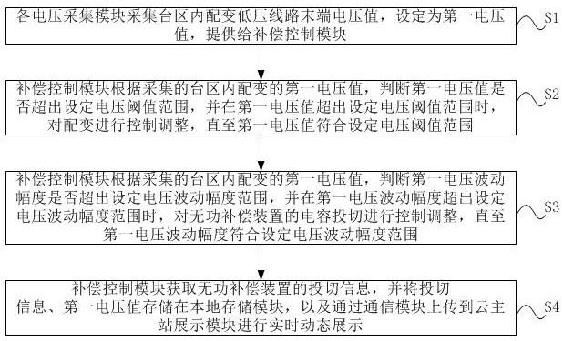
[0074] Such as figure 2 As shown, the present invention provides a compensation method based on the reactive power compensation system in the above-mentioned embodiment 1 or 2, including the following steps:
[0075] S1. Each voltage acquisition module collects the terminal voltage value of the distribution transformer low-voltage line in each station area, sets it as the first voltage value, and provides it to the compensation control module;
[0076] S2. The compensation control module judges whether the first voltage value exceeds the set voltage threshold range according to the collected first voltage value of the distribution transformer in the station area, and when the first voltage value exceeds the set voltage threshold range, the distribution transformer is checked. controlling and adjusting until the first voltage value meets the set voltage threshold range;
[0077] S3. The compensation control module judges whether the first voltage fluctuation range exceeds the...
PUM
 Abstract
Description
Claims
Application Information
 - R&D
- Intellectual Property
- Life Sciences
- Materials
- Tech Scout
- Unparalleled Data Quality
- Higher Quality Content
- 60% Fewer Hallucinations
Browse by: Latest US Patents, China's latest patents, Technical Efficacy Thesaurus, Application Domain, Technology Topic, Popular Technical Reports.
© 2025 PatSnap. All rights reserved.Legal|Privacy policy|Modern Slavery Act Transparency Statement|Sitemap|About US| Contact US: help@patsnap.com