Circuit assembly module seat separating device

A technology for separating devices and circuit components, which is applied in connection/disconnection of connection devices, recycling of electronic waste, recycling technology, etc., and can solve problems such as difficulty in disassembly, inability to ensure vertical upward, easily damaged multi-pin stack socket pinholes, etc. , to achieve the effect of expanding the scope of use, convenient and fast adjustment and clamping, and labor-saving operation

Active Publication Date: 2021-06-22
HUBEI SANJIANG AEROSPACE HONGFENG CONTROL
View PDF5 Cites 1 Cited by
  • Summary
  • Abstract
  • Description
  • Claims
  • Application Information

AI Technical Summary

Problems solved by technology

[0002] The circuit component module is composed of a printed board connected up and down through a multi-pin stack socket to form a module seat. During the test, each module needs to be assembled and disassembled repeatedly, and the circuit components between the modules are closely connected up and down by a multi-pin stack socket, which makes disassembly difficult.
In the actual disassembly, there is no corresponding tool, so many people need to pull it out manually. One person hugs the module and presses the lower frame of the lower module to be separated, and the other person grabs the upper frame of the upper module to be separated by hand, because the width of the module frame is narrow and It cannot be guaranteed to be vertically upward during operation, and it needs to be shaken from side to side and pulled upward hard, which is laborious and easy to damage the pinholes of the multi-pin stack socket

Method used


Image

  • Circuit assembly module seat separating device
  • Circuit assembly module seat separating device
  • Circuit assembly module seat separating device

Examples


Embodiment Construction

[0026] The technical solutions of the present invention will be clearly and completely described below in conjunction with the accompanying drawings of the present invention. Based on the embodiments of the present invention, all other embodiments obtained by persons of ordinary skill in the art without making creative efforts fall within the protection scope of the present invention.

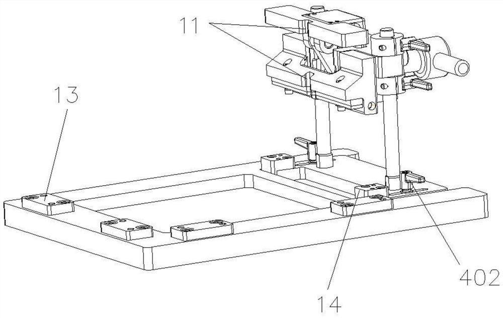
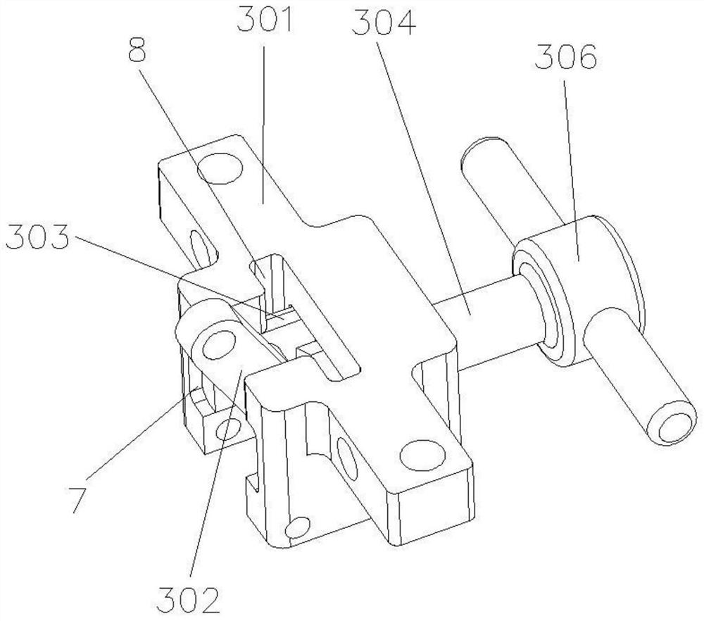
[0027] Such as Figure 1 to Figure 8 The circuit assembly module seat separation device shown includes a base 1, a positioning plate assembly 2, a hinge seat assembly 3, a fixing ring assembly 4, a pressure plate assembly 5 and a top plate assembly 6, and the positioning plate assembly 2 is fixedly connected to the base 1 , the positioning plate assembly 2 includes a guide rod 201, the hinge seat assembly 3 is locked on the guide rod 201 through the fixing ring assembly 4, the pressure plate assembly 5 and the top plate assembly 6 are arranged up and down oppositely, and the pressure plate asse...


PUM


Abstract

The invention discloses a circuit assembly module seat separating device, which comprises a base, a positioning plate assembly, a hinge seat assembly, a fixing ring assembly, a pressing plate assembly and a top plate assembly, and is characterized in that the positioning plate assembly is fixedly connected with the base, the positioning plate assembly comprises a guide rod, the hinge seat assembly is locked on the guide rod through the fixing ring assembly, and the pressing plate assembly is fixedly connected with the base. The pressing plate assembly and the top plate assembly are oppositely arranged up and down, the pressing plate assembly is fixedly connected with the hinge seat assembly, and the top plate assembly is hinged to the hinge seat assembly and is driven by the hinge seat assembly to slide up and down along the hinge seat assembly. The separating device can realize effective separation of the circuit assembly module without damaging the surface of the module and a socket pinhole, and is reliable in pressing and separating action, labor-saving in operation and wide in application range.

Description

technical field [0001] The invention relates to the technical field of circuit component module testing, in particular to a circuit component module seat separation device. Background technique [0002] The circuit component module consists of a printed board connected up and down through a multi-pin stacked socket to form a module seat. During the test, each module needs to be assembled and disassembled repeatedly, and the circuit components between the modules are tightly connected up and down with a multi-pin stacked socket, which makes disassembly difficult. In the actual disassembly, there is no corresponding tool, so many people need to pull it out manually. One person hugs the module and presses the lower frame of the lower module to be separated, and the other person grabs the upper frame of the upper module to be separated by hand, because the width of the module frame is narrow and It cannot be guaranteed to be vertically upward during operation, and it needs to be...

Claims


Application Information

Patent Timeline
Patent Type & Authority Applications(China)
IPC IPC(8): H01R43/26
CPCH01R43/26Y02W30/82
Inventor 赵文峰孙武斌严芙蓉方兵车飞
Owner HUBEI SANJIANG AEROSPACE HONGFENG CONTROL
Why Eureka
Try Eureka