Area array CCD imaging and photoelectric coding combined fragment group testing device and method

A photoelectric encoding and testing device technology, which is applied in the direction of measuring devices, optical devices, ammunition tests, etc., can solve the problems of large material consumption, failure to identify heavy holes, and affect the accurate acquisition of multi-fragment parameters, etc., and achieve a simple device structure. Effect

Active Publication Date: 2021-06-22
XIAN TECHNOLOGICAL UNIV
View PDF1 Cites 1 Cited by
  • Summary
  • Abstract
  • Description
  • Claims
  • Application Information

AI Technical Summary

Problems solved by technology

Although the wooden target method has high reliability, it consumes a lot of materials, is inconvenient to install, cannot identify heavy holes, takes time and effort, not only cannot achieve real-time data processing, but also cannot eliminate human errors due to manual measurement; multiple light curtains intersect The test system uses the intersecting arrangement of array detection light curtains to measure the target position. If at least seven detection light curtains are required to test the fragment group, multiple fragments can be identified and matched by detecting the spatial geometric relationship of the light curtains. The structure of the test system and The algorithm is relatively complicated, and it is impossible to achieve precise arraying in actual engineering, which affects the accurate acquisition of

Method used


Image

  • Area array CCD imaging and photoelectric coding combined fragment group testing device and method
  • Area array CCD imaging and photoelectric coding combined fragment group testing device and method
  • Area array CCD imaging and photoelectric coding combined fragment group testing device and method

Examples


Embodiment 1

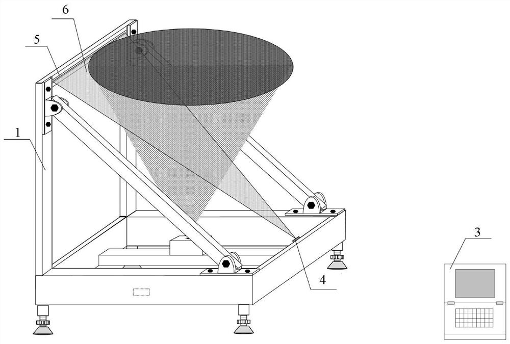
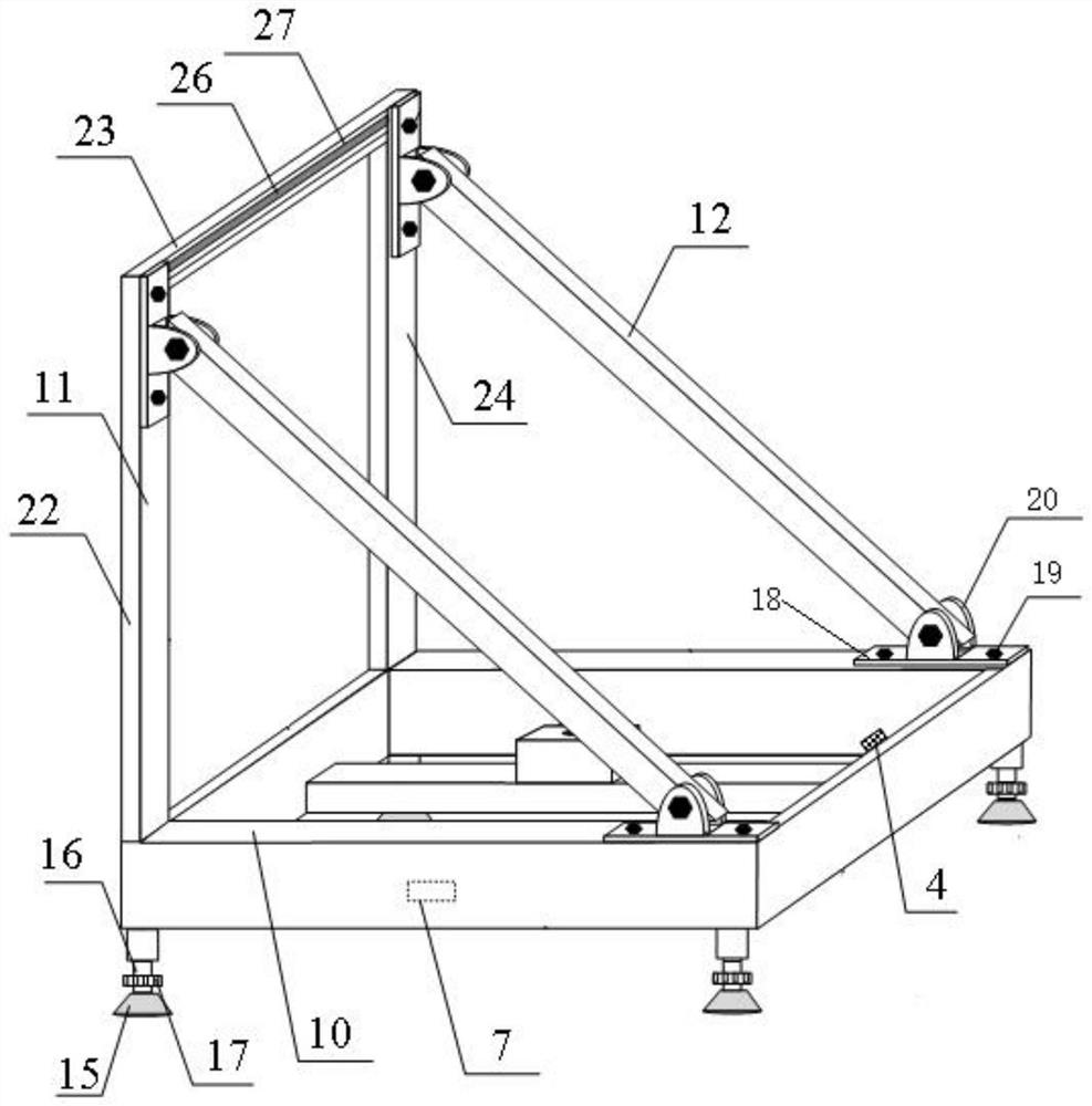
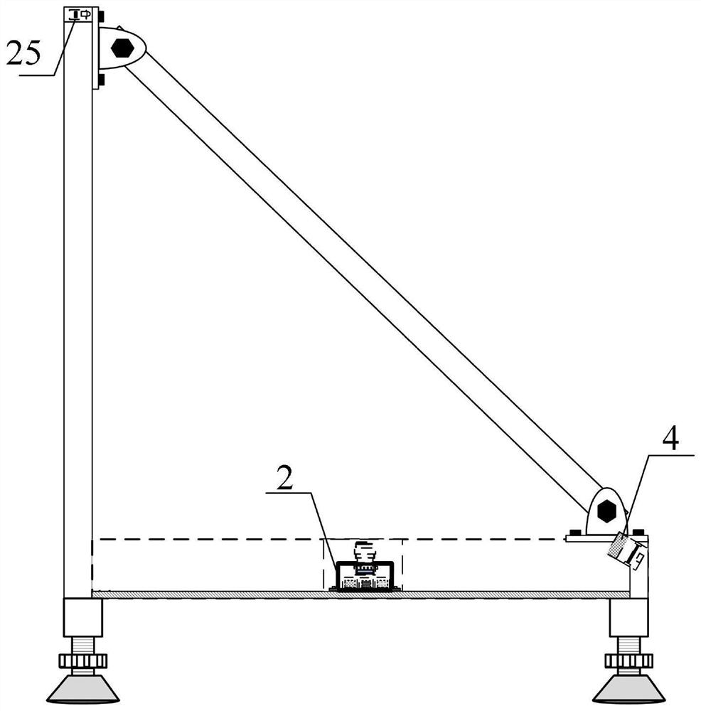
[0047] The present invention provides a fragment group test device combined with area array CCD imaging and photoelectric encoding. The test device uses a combination of line laser 4, photodiode encoding array 5 and area array CCD target 2 to measure the spatial distribution parameters of fragment groups. carry out testing. like figure 1 As shown, it includes an L-shaped main frame 1, an area array CCD target 2, and a host computer 3; a photodiode code array 5 is arranged in the middle of the top of one side of the main frame 1, and a photodiode code array 5 is arranged in the middle of the bottom of the other side away from the photodiode code array 5. Wired laser 4, through the line laser 4 emits a "one"-shaped laser beam obliquely upward to form a laser detection light curtain 6, and the photosensitive diode code array 5 receives the laser beam as a photodetection unit to form a laser detection light curtain 6; area array CCD target 2. Set at the center of the bottom of th...


PUM


Abstract

The invention provides an area array CCD imaging and photoelectric coding combined fragment group testing device and method, and belongs to the technical field of photoelectric testing and weapon target range testing. The testing device comprises a main body frame, an area array CCD target and an upper computer; a line laser and a photosensitive diode coding array are arranged in the main body of the testing device; the line laser is located at the right end of the lower portion of the main body frame of the testing device; the laser light source and the photosensitive diode coding array at the right upper end of the main body frame of the testing device form a detection light curtain; and the area array CCD target is installed in the center of the bottom of the main body frame; and the field of view of the area array CCD target intersects with the laser detection light curtain; and the main body of the testing device is arranged in a ballistic direction and is a certain distance away from the explosion position of a warhead. According to the device and method, a fragment group generated by bullet explosion can be accurately matched and identified, fragment space distribution parameters can be measured in a high-precision manner, and effective data support is provided for target damage efficiency evaluation.

Description

technical field [0001] The invention belongs to the technical fields of photoelectric testing and weapon shooting range testing, and in particular relates to a fragment group testing device and method combined with area array CCD imaging and photoelectric coding. Background technique [0002] The spatial distribution of fragments is one of the important parameters for evaluating the damage effect of warheads, especially the evaluation of the damage effectiveness of space projectiles near-exploded fragments on space targets. Due to the randomness and uncertainty of the fragment group generated at the moment of explosion, the spatial distribution of fragments Therefore, it is of great research significance to measure the spatial distribution parameters of fragments with high precision, and provide an effective theoretical basis for the target damage evaluation system. [0003] At present, the test devices for fragment dispersion parameters mainly include wooden target board, m...

Claims


Application Information

Patent Timeline
IPC IPC(8): G01B11/00F42B35/00
CPCG01B11/002F42B35/00
Inventor 李翰山张晓倩魏飞张雪薇
Owner XIAN TECHNOLOGICAL UNIV
Why Eureka
Try Eureka