Air compressor with efficient heat dissipation capacity and control method thereof

A technology of heat dissipation capacity and air compressor, applied in pump control, chemical instruments and methods, mechanical equipment, etc., can solve the impact of axial flow fan blades and centrifugal fan rotor service life, the loss of heat dissipation function of air compressor, accelerated air pressure Air circulation and other problems of the machine, to achieve the effect of easy installation and disassembly, easy maintenance and replacement, and reduce pollution

Pending Publication Date: 2021-06-22
胡红婷
View PDF1 Cites 3 Cited by
  • Summary
  • Abstract
  • Description
  • Claims
  • Application Information

AI Technical Summary

Problems solved by technology

In order to solve the problem of heat dissipation, the air compressor is changed, and the air circulation inside the air compressor is accelerated through the axial flow fan blade and the centrifugal fan wheel, so as to effectively reduce the temperature inside the air compressor. However, the above air compressor is in use There is also the problem of insufficient heat dissipation, and the axial fan blades and centrifugal fan wheels of the air compressor rotate with the shaft. Once the motor controlling the axial flow fan blades and centrifugal fan wheels is damaged, the air compressor will lose The heat dissipation function of the air compressor, and the heat dissipation device of the air compressor cannot change the speed with the change of the temperature of the air compressor. Efficient control of blades and centrifugal rotors

Method used


Image

  • Air compressor with efficient heat dissipation capacity and control method thereof
  • Air compressor with efficient heat dissipation capacity and control method thereof
  • Air compressor with efficient heat dissipation capacity and control method thereof

Examples


Embodiment Construction

[0045] In order to enable those skilled in the art to better understand the technical solutions in the present invention, the technical solutions in the embodiments of the present invention are clearly and completely described below in conjunction with the accompanying drawings:

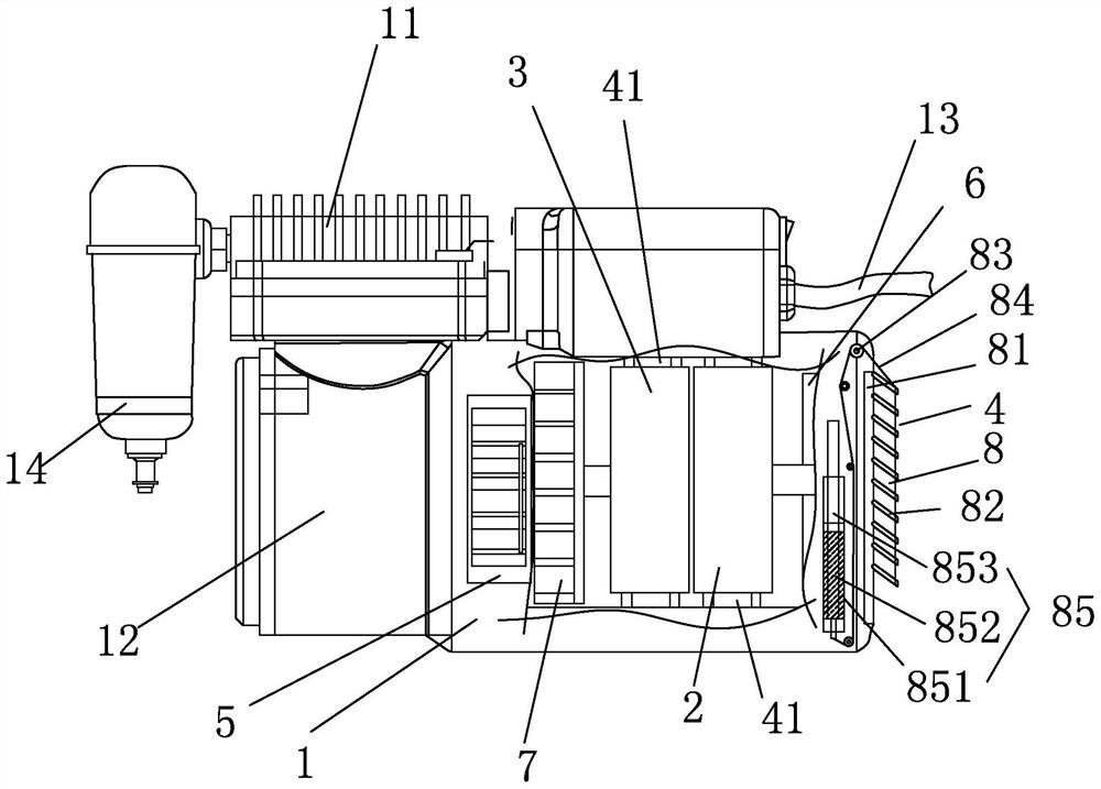
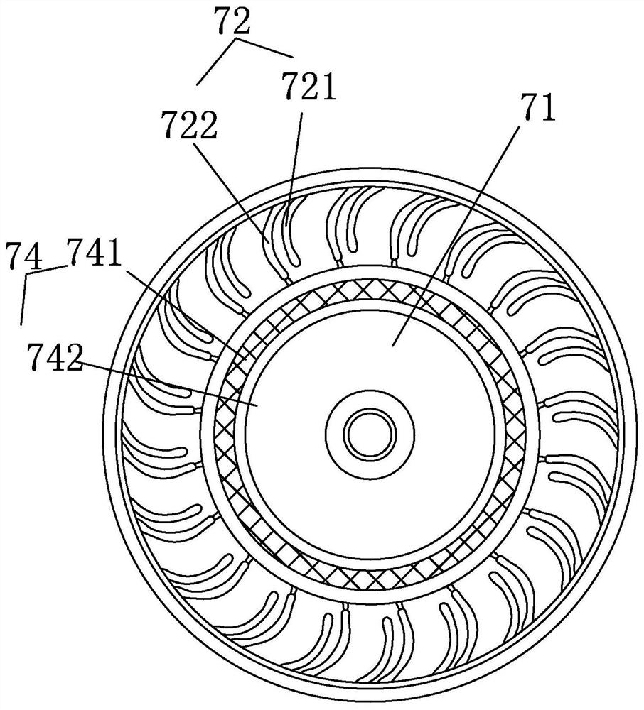
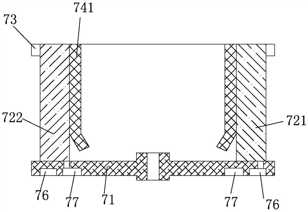
[0046] Such as Figure 1 to Figure 3 As shown, an air compressor with high-efficiency heat dissipation includes a casing 1, a first motor 2, a second motor 3, a cylinder 11, an air pump, and a power cord 13. The air pump is arranged on one side of the casing 1, and the cylinder 11 is arranged above the air pump, one end of the output shaft of the first motor 2 is provided with a cooling fan 6, the casing 1 is provided with an air inlet 4, and the air inlet 4 is used to supply air to the cooling fan 6, the second motor 3 and the air pump A centrifugal impeller 7 is arranged between them, and an air outlet 5 is provided on the casing 1, and the air outlet 5 is used to discharge the air in the casing 1,...


PUM


Abstract

The invention discloses an air compressor with an efficient heat dissipation capacity. The air compressor comprises a machine shell, a first motor, a second motor, an air cylinder, an air pump and a power line; the air pump is arranged on one side of the machine shell; the air cylinder is arranged above the air pump; a cooling fan is arranged at one end of an output shaft of the first motor; an air inlet is formed in the machine shell and used for supplying air to the cooling fan; a centrifugal impeller is arranged between the second motor and the air pump; an air outlet is further formed in the machine shell and used for exhausting air in the machine shell; a ventilation flow channel is further formed between the first motor and the second motor and enables the air inlet and the air outlet to be communicated; the centrifugal impeller comprises a disc body, blades and a reinforcing frame; the blades are arranged in an inclined mode; the bottom faces of the blades are fixed to the disc body; the side walls of the upper half portions of the blades are fixed to the reinforcing frame; each blade is composed of an auxiliary blade set and a main blade set; and the auxiliary blade sets and the main blade sets are distributed at intervals and do not generate currents mutually.

Description

technical field [0001] The invention belongs to the technical field of air compressor equipment, and in particular relates to an air compressor with high-efficiency heat dissipation capability and a control method thereof. Background technique [0002] An air compressor is an air power source that uses an electric motor to drive an air pump to generate air pressure. It is a device that converts the mechanical energy of the motor into gas pressure energy, and is a device that generates air pressure for compressed air. The air compressor is a miniature reciprocating piston compressor. Its working principle is: when the motor uniaxially drives the crankshaft of the compressor to rotate, through the transmission of the connecting rod, the piston with self-lubrication without adding any lubricant will reciprocate. The working volume formed by the inner wall of the cylinder, the cylinder head and the top surface of the piston will change periodically. With the increasing diversi...

Claims


Application Information

Patent Timeline
Patent Type & Authority Applications(China)
IPC IPC(8): F04D25/06F04D29/28F04D29/30F04D29/42F04D29/44F04D29/58F04D29/70F04D29/62F04B39/06F04B49/06B03C3/00
CPCB03C3/00F04B39/06F04B49/065F04D25/06F04D29/282F04D29/30F04D29/4206F04D29/441F04D29/582F04D29/626F04D29/703
Inventor 不公告发明人
Owner 胡红婷
Why Eureka
Try Eureka