
Self-stabilization control method and system for tower crane

A control method and control system technology, which is applied in the field of tower crane self-stabilization control method and system, can solve problems such as construction personnel's personal safety, excessive shaking amplitude, tower crane overturning, etc., so as to prevent construction personnel's personal safety and prevent The effect of tower crane overturning problem

Active Publication Date: 2021-06-22
北京拓疆者智能科技有限公司
View PDF6 Cites 4 Cited by
  • Summary
  • Abstract
  • Description
  • Claims
  • Application Information

AI Technical Summary

Problems solved by technology

[0004] However, the above-mentioned patented technology only controls the stability of the tower crane from the perspective of the mechanical structure and the electronic system monitoring the inclination of the tower body
However, if the suspended object has a large shaking amplitude and excessive swing during the hanging and transportation process, it may cause personal safety problems for nearby construction workers, and cause the tower crane to overturn, resulting in serious safety production accidents.
[0005] At present, there is no way to actively control the suspended object to stabilize the suspended object if there is a large shaking amplitude or excessive swing during the suspension and transportation process.

Method used


Image

  • Self-stabilization control method and system for tower crane
  • Self-stabilization control method and system for tower crane
  • Self-stabilization control method and system for tower crane

Examples


Embodiment 1

[0045] The final effect of the self-stabilizing control expected to be achieved by the present invention is to press a button to quickly stabilize the objects lifted by the tower crane. To achieve this effect, the tower crane needs to be designed accordingly.

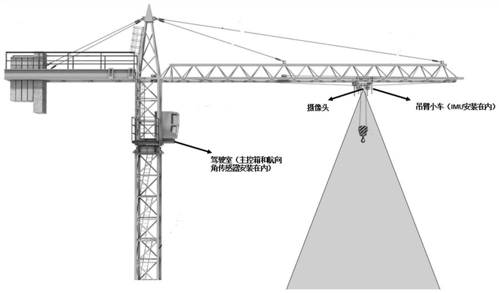
[0046] Specifically, such as figure 1 As shown, a kind of tower crane self-stabilizing control system of the present invention comprises:

[0047]The cab installed on the tower body, the main control box and heading sensor are installed in the cab;

[0048] The boom trolley installed on the boom, an inertial measurement unit is installed inside the boom trolley, and a camera facing the hook is installed on the lower part of the boom trolley; wherein,

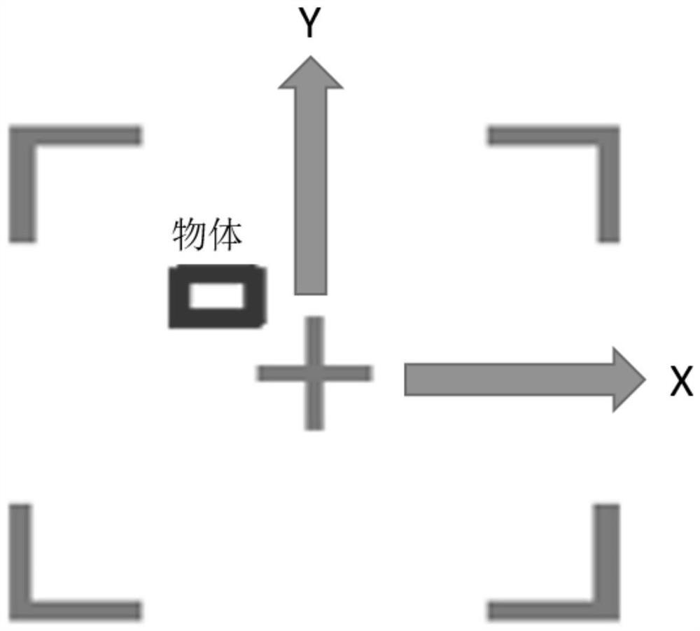
[0049] The camera obtains the image of the object on the hook in real time and sends it to the main control box. The inertial measurement unit obtains the acceleration, speed and position information of the boom trolley in real time and sends it to the main control box. ...

Embodiment 2

[0053] Corresponding to Embodiment 1, this embodiment provides a tower crane self-stabilizing control method, including:

[0054] S1. Obtain the image of the object on the hook in real time;

[0055] S2. Obtain the acceleration, speed and position information of the boom trolley in real time;

[0056] S3, obtaining the angular acceleration, angular velocity and angle of the rotation of the tower crane in real time;


PUM


Abstract

The invention discloses a self-stabilization control method and system for a tower crane. The system comprises a cab installed on a tower body, and a main control box and a course sensor are installed in the cab; a suspension arm trolley is installed on a suspension arm, an inertia measurement unit is installed in the suspension arm trolley, and a camera facing the lifting hook is installed on the lower portion of the suspension arm trolley; wherein the camera acquires an image of an object on a lifting hook in real time and sends the image to the main control box, the inertial measurement unit acquires acceleration, speed and position information of the suspension arm trolley in real time and sends the information to the main control box, and the course sensor acquires angular acceleration, angular speed and angle of rotation of the tower crane in real time and sends the angular acceleration, angular speed and angle to the main control box; and the main control box analyzes the real-time position of the object according to the object image, controls the movement of the suspension arm trolley and the suspension arm according to the deviation of the real-time position of the object from the preset range, so that the real-time position of the object is within the preset range. When the object deviates from the preset range, the hoisted object is quickly stabilized, so that the possible personal safety problem of constructors and the possible overturning problem of the tower crane are prevented.

Description

technical field [0001] The invention relates to the technical field of tower crane accessories, in particular to a tower crane self-stabilizing control method and system. Background technique [0002] At present, the balance of most tower cranes is completed by counterweights. The counterweights are adjusted according to the hoisting weight to complete the entire balance system, but the overall balance is passive and the stability is poor. There will be a certain range when hoisting heavy equipment. The swing, and the ability to resist strong winds is also weak, and the overall balance performance is not good. [0003] The existing Chinese invention patent CN104495643A discloses a tower crane active stability maintenance system, which is mainly composed of a longitudinal block, a transverse block, a steel cable and a balance ellipsoid, and the longitudinal pulleys on both sides of the longitudinal block are installed in the pulley groove of the tower crane arm Above, the tr...

Claims


Application Information

Patent Timeline
Patent Type & Authority Applications(China)
IPC IPC(8): B66C13/06B66C13/48B66C23/88
CPCB66C13/063B66C13/48B66C23/88
Inventor 李子实隋少龙
Owner 北京拓疆者智能科技有限公司
Learn More